
In the last episode We had looked at the Motor-Shield and the basics of stepper motor control. The Shield is ideal for understanding the tax processes because you can follow the progress, every step. Only if you have bigger things, then the circuit effort quickly becomes larger and more than half -step is not in it without rapidly growing programming effort. You don't necessarily have to "reinvent the wheel", because there are professional solutions from Allegro and Texas Instruments (Ti). The A4988 from Allegro and also the DRV8825 from Ti are not even half the size of an ESP8266 D1 mini and offer a whole bundle of good properties that the motor shield does not have.

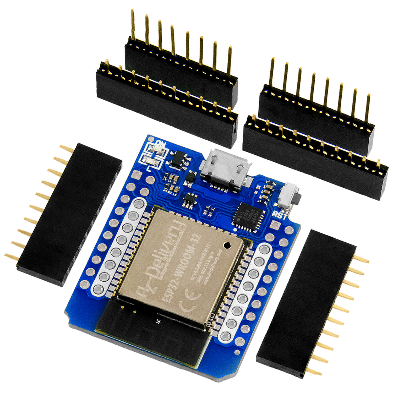
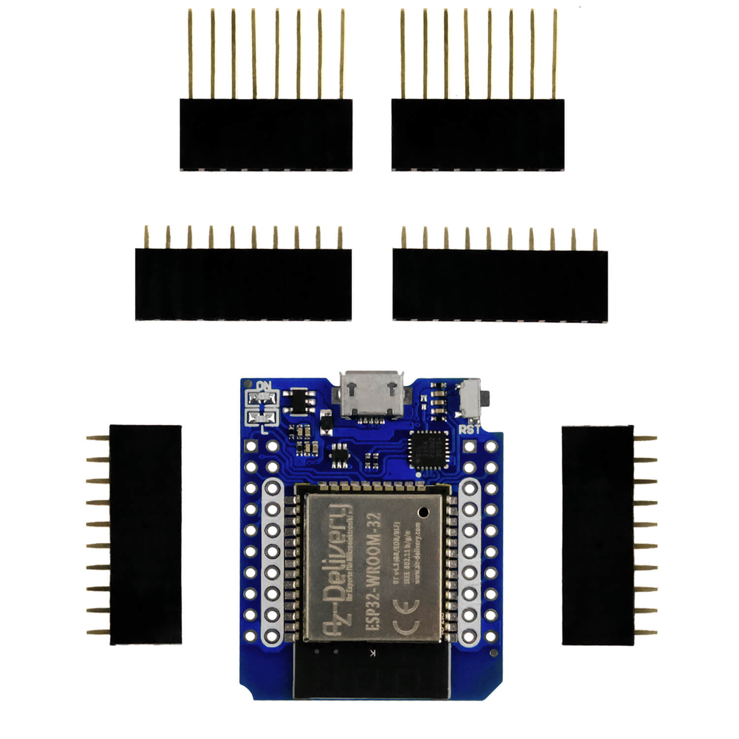
Figure 1: An A4988 on the ESP8266 - Size comparison
Today we will take a close look at the two driver modules and build a Micropython program module to control them. It was important to me to involve all the essential parameters that offer the small crisps. In addition to the GPIOS 4, 5 and 16, all pins of the ESP8266 D1 Mini, which I use in this application example as a controller, are documented. Of course, the Amica be taken from the last post. The Micropython module works both in interrupt operation and manually. Let yourself be surprised with this new episode
Micropython on the ESP32 and ESP8266
today
Chic drivers for stepper motors
I start with a short addendum for the previous episode. There I had undertook the first experiments on the Motor-Shield with two step motors from an old printer. One of the two was obviously defective and so I decided to explore the interior. In Figure 2 you can clearly identify the two coils of a bipolar engine. It is obviously a permanent magnet step-in engine. The rotor is a ferrite magnet. It is interesting to produce and distribute the poles of the statormagnet. North and south poles alternate each other through skillful arrangements. In this way, 24 steps can be achieved with the engine with only two windings. So the step width is 15 °.

Figure 2: Inner life of a bipolar permanent magnet step-step engine
After the brief review now to today's program. Let us first examine the two modules more precisely.
The driver modules
Both boards are delivered ready with two 8-pole bushes and a small heat sink. I read somewhere that the heat sink is only necessary from about 1.2a. With the engines used here, the current is well below half an amper, so you can confidently leave it out.
A warning in advance: The chips are provided with protection against overheating, which switches off the current to the motor winding when a temperature of 150 ° C (Allegro data sheet) is achieved. That is already a whole end to burn your fingers.
The A4988 from Allegro

Figure 3: A4988 driver module
The dimensions are very small, just 15.3 x 20.4 mm. The distance between the pen strips is 5 grid units. This means that the boards easily fit on a Breadboard. The connection assignment of the A4988 is as follows:

Figure 4: A4988 - Pinout
The chip needs two operating stresses, VM For the engine and VDD for the logic part. VM Should be in the range of 8.2V to 35V and VDD Between 3.3V and 5.5V. The current strength through the motor windings may be up to 2a.
The H-bridges already known to us immediately catch the eye when you look at the block circuit diagram of the driver chip. Connections 2b, 2a and 1b, 1a lead to the coils of a bidirectional stepper motor. Unipolar engines cannot control the board.
There are two standard resistance on the board Rs1 and Rs2 From 0.1Ω in the mass line to the H-bridges. They serve the electricity measurement for the current limitation. This ensures that VM Higher tensions can be created than the calculation U = imax • RSP. We come back to it later.

Figure 5: Block circuit diagram of the A4988 (data sheet from Allegro)
The tax inputs are all on the left side of the board. So that the H-bridges can become active at all, the entrance must -Enable be placed on 0V. The ESP8266 on GPIO14 (D5) takes on this task. If there is a logical 1 on this input, the H-bridges are switched off, the translator and the rest of the logic remain active. The entrance is kept with a pulldown resistance from 100kΩ to logical 0 if it is not switched externally.
The entrance -Sleep Moves the chip into sleep mode. All circuits are switched off, including the H-bridges when the entrance is placed on GND potential. Internally, it is placed on VCC with a pull-up resistor of 100kΩ.
We connect -Sleep With the entrance -Areset. With this the pullup affects -Sleep also as a pullup for -Areset. We will not control both inputs. The pullup keeps the chip on work.
The level on YOU Specifies the direction of rotation. I connected the engine so that a 1 turn in clockwise and a 0 in the opposite clock. We control the direction via GPIO2 (D4).
With an increasing flank Step If the engine leads a step in the YOU set direction. The pulse come GPIO0 (D3). Because neither you nor Step internal pullups or pulldowns, we can easily connect them to GPIO0 and GPIO2 without disturbing or changing the starting behavior of the ESP8266. This point is crucial for GPIO15 (D8) to which the M3 mode line is connected and which must be logical 0 when booting.
You can use the Pins M1, M2 and M3, which are provided with pulldown resistors Microstepping set. What is that? In the previous blog post We have already discussed the half-step process, in which the rotor is only moved by half a step angle by overlapping, switching on and off the motifs.

Figure 6: Half -step operation (with the unipolared motor)
If you set the electricity through the coils in stages to values between and out, then you can reach a step angle that only correspond to part of the full angle. The entire cycle for the full step is thus divided into several sections, phases, for which the full 100% force effect on the anchor should result, but also no longer. With the Motorshield we actually achieved 141% in the interaction of two activated coils without reduced electricity, because if each coil works in Figure 6 with 100%, we receive with the formula

Figure 7: Calculation of the overall current
100%² + 100%² = 20,000 and the root from it makes 141%. The A4988 reduces the current in half -step mode to 70%by pulse width modulation (PWM).

Figure 8: Half -step mode via coil current control
But how do you get the 70%? Quite simply, with a little math.

Figure 9: The percentage values result from the sub -angles
In the case of half -step, the rotor should stop exactly between the two coils, i.e. to 45 °. The sinus and cosine function both deliver the value 0.7071. These are the lengths of the green and blue line when the red arrow is said to have length 1. We get to the percentage when we multiply every value with 100%. It is the same with quarter-step mode, we get the step angle 0 °, 22.5 ° 45 °, 67.5 ° and 90 °. Sinus and cosine provide the corresponding values for electricity reduction.
If refined further, the course of the electricity curves approaches the graph of the sinus and cosine function. Of course, this also works with the coil pairs for bipolar engines.

Figure 10: Microstepping with the DRV8825 (data sheet of Ti)
Depending on the circuit of the M1, M2 and M3 mode inputs on the A4988, you can set microstepping up to 16-tin steps. The advantages with a finer step division are of course primarily the better angle resolution and the quieter run because vibrations are avoided when braking. When stopping the rotor after a larger step, a subdued vibration arises when it swings around the stop position until it finally comes to a standstill.

Figure 11: Modus control at A4988
With the small trimmer you can set the current strength border through the engine windings. The maximum power strength inax is calculated from the tension measured on the handle (red arrow)
Imax = vref / (8 • rs)
RS are the series resistors R4 and R5 of 0.1Ω in the mass line of the H-bridges (right next to the chip), which work as current strengthensors.

Figure 12: A4988 - measuring point
The current can of course also be measured directly. In this case, be sure to collect the motor voltage first. Then disconnect a strand and connect an amperemeter. After switching on the motor voltage, activate the chip and read the current strength value. With the trimmer you set the desired current. Before removing the measuring device, switch off the motor voltage again!
The DRV8825
The DRV8825 can process tensions up to 45V. No heat sink is required for strand current thicknesses of up to 1.5a, according to the data sheet, current strengths up to a maximum of 2.5A is permitted. Due to the current limitation, tensions can be placed on the windings that are higher than they are specified or calculated for the engine. A higher motor voltage results in a higher torque when switching on the winding. The current limitation still protects the windings from overload.
The driver module with the DRV8825 from Ti corresponds to the A4988 to a little something in size and pinout. The tax inputs and coil outputs are in the same position and have the same function, but a slightly different internal circuit. The PIN -Sleep has a pullup in the A4988, here it is drawn to GND with 1MΩ. However, the main difference lies in the power supply. The DRV8825 only requires a motif, from which it derives the lower voltage for the logic itself.

Figure 13: DRV8825 module

Figure 14: DRV8825 - Pinout
The output lies on the pin to which the logic voltage is fed to the A4988 -Fault. This is drawn to GND potential if the DRV8825 determines a malfunction, such as overcurrent, overheating, short circuit or too low operating voltage. It needs an external pullup.

Figure 15: Fault and Sleep circuit
To -Flt lies with the board of the +VDD-Pin of the A4988. Therefore, the PIN gets the 3.3V from the ESP8266 if you replace the A4988 with a DRV8825. The 10kΩ resistance serves as a pullup on the PIN -Slp and also pulls the entrance -Sleep on the DRV8825 chip. Should still -Fault Go to logical 0, then the 1.5kΩ resistance secures the circuit against a short circuit.
The strandtom thickness can also be adjusted with the trimmer in the DRV8825, but with a different value for the factor A. by measuring the coil current (203mA), the reference voltage (209mv) and RS = 0.1Ω, I do not come as stated in the data sheet, on a = 5 but on a = 10. The reference voltage is measured again on the handle of the trimmer (red arrow).
Imax = vref / (a • rs)
Therefore, I recommend measuring the coil current directly. Caution! Always switch off the motor voltage before a motor winding is separated.

Figure 16: DRV8825 - measuring point
The microstepping is based on a somewhat changed table. The pins are also numbered differently. The DRV8825 can be programmed up to a 32-stele step.

Figure 17: Modus control at DRV8825
For both modules, follow the following pulse scheme to initiate a step or micro -step.

Figure 18: Impulse sequence on DRV8825 and A4988
-Sleep If we are always in logical 1, the sweater of 10kΩ ensures this. After -Enable has been set to logically 0, we set the direction and the micro -ride mode. After that, with every positive flank on the PIN Step a step triggered.
Hardware
According to the theory, it is now becoming craftsmanship. The following parts are necessary to set up the circuit.
| 1 | ESP32 Dev Kit C unpleasant or ESP32 NODEMCU Module WiFi Development Board or Nodemcu-ESP-32S kit or Nodemcu Lua Amica Module V2 or ESP8266 ESP-01S WiFi WiFi module or D1 Mini V3 Nodemcu with ESP8266-12F |
|---|---|
| 1 | A4988 Step motor driver module with heat sink |
| or DRV8825 Step motor driver module with heat sink | |
| 1 | Breadboard Kit - 3x Jumper Wire M2M/F2M/F2F + 3 Set MB102 Breadbord Compatible with Arduino and Raspberry Pi - 1x Set |
| 1 | Stet engine uni or bipolar e.g. Pollin order no. 310689 or 310690 |
| various | Jumper cable |
| Optional | Logic Analyzer |
The Logic Analyzer is very useful when it comes to monitoring the logic lines.
The software
For flashes and the programming of the ESP32:
Thonny or
pack box To test the ESP8266 as a UDP client and server
Saleae – Logic analyzer software (64 bit) For Windows 8, 10, 11
Used firmware for an ESP32:
Used firmware for an ESP8266:
The micropython programs for the project:
stepper.py Micropython module
Micropython - Language - Modules and Programs
To install Thonny you will find one here Detailed instructions (English version). There is also a description of how that Micropython firmware (As of 05.02.2022) on the ESP chip burned becomes.
Micropython is an interpreter language. The main difference to the Arduino IDE, where you always flash entire programs, is that you only have to flash the Micropython firmware once on the ESP32 so that the controller understands micropython instructions. You can use Thonny, µpycraft or ESPTOOL.PY. For Thonny I have the process here described.
As soon as the firmware has flashed, you can easily talk to your controller in a dialogue, test individual commands and see the answer immediately without having to compile and transmit an entire program beforehand. That is exactly what bothers me on the Arduino IDE. You simply save an enormous time if you can check simple tests of the syntax and hardware to trying out and refining functions and entire program parts via the command line before knitting a program from it. For this purpose, I always like to create small test programs. As a kind of macro, they summarize recurring commands. Whole applications then develop from such program fragments.
Autostart
If the program is to start autonomously by switching on the controller, copy the program text into a newly created blank tile. Save this file under boot.py in WorkSpace and upload it to the ESP chip. The program starts automatically the next time the reset or switching on.
Test programs
Programs from the current editor window in the Thonny-IDE are started manually via the F5 button. This can be done faster than the mouse click on the start button, or via the menu run. Only the modules used in the program must be in the flash of the ESP32.
In between, Arduino id again?
Should you later use the controller together with the Arduino IDE, just flash the program in the usual way. However, the ESP32/ESP8266 then forgot that it has ever spoken Micropython. Conversely, any espressif chip that contains a compiled program from the Arduino IDE or AT-Firmware or Lua or ... can be easily provided with the micropython firmware. The process is always like here described.
The Micropython module
In the module I was able to do the classes for the DRV8825 and the A4988 Association because the two chips are almost the same. As we already know, there are only different mode tables. Ultimately, this also affects the method set fashion() from which the mode pins sets. I elegantly solved the problem by simply the class DRV8825 from the class A4988 inherit and both the table Fashionable And the method set fashion() just overwrite.
# Stepper.py
# Driver for bidirectional engines with A4988 / DRV8825
# Am ESP8266
#Lua-Pins D0 D1 D3 D4 D5 D6 D7 D8 RX TX
#ESP8266 Pins 16 5 4 0 2 14 13 15 3 1
#beim start hi sc sd hi hi lo hi hi
#Pin assignment st di en m1 m2 m3
#
# Dir, Step, Enable = 2.0.14 (D4, D3, D5)
# Sleep + RST are due to VCC
#
# M1, M2, M3 = 12.13.15 (D6, D7, D8)
From machine import Pin, timer
From time import Sleep_ms,Sleep_us
From the module machine we need Pin and timer and of time Sleep_ms and Sleep_us For small breaks.
I explain some classes for error treatment that I have from the base class Exception Discharge.
XXXXXXXXXX
class A4988_error(Exception):
passport
class Microstepping_error(A4988_error):
def __init__(self):
super().__init__("Wrong Microstepping!",
"Use 1, 2, 4, 8 or 16")
class Direction_error(A4988_error):
def __init__(self):
super().__init__("Wrong Direction Value!",
"Use -1, 0 or 1")
With the class ending of A4988, I also define the class attribute Fashionable. The keys in Dictionary are the step divider and in threeTuber Follow the logical values for mode pins.
XXXXXXXXXX
class A4988(A4988_error):
Fashionable={
1:(0,0,0),
2:(1,0,0),
4:(0,1,0),
8:(1,1,0),
16:(1,1,1),
}
The constructor is the most extensive method of class. This is due to the numerous attributes, the objects to be created. As a parameter, I hand over the pin numbers of the GPIOs, as well as the number of steps for a revolution and then create the PIN objects. I put the pins for the modus control in one list, so that I can refer you later in a for loop about the index.
XXXXXXXXXX
def __init__(self,
You=2,
Step=0,
Enable=14,
M0=12,
M1=13,
M2=15,
Stepsperrev=24,):
self.you=Pin(You,Pin.OUT, value=0)
self.step=Pin(Step,Pin.OUT, value=0)
self.en=Pin(Enable,Pin.OUT, value=1)
self.fashion=[
Pin(M0,Pin.OUT,value=0),
Pin(M1,Pin.OUT,value=0),
Pin(M2,Pin.OUT,value=0),
]
self.direct=0 # Standstill
self.freq=10000 # Timer frequency
self.delay=1000 # Module for frequency division
self.velocity=self.freq//self.delay # Speed
self.count=0 # Repetitional error in the ISR
self.apos=0 # current position
self.TPOs=0 # Target position
self.timer=timer(0) # Timer for IRQ
self.timerary=False # Flag f. Timer on / off
self.Stepsperrev=Stepsperrev # Steps per round
self.quilting=1 # Microschritt mode
self.degpertystep=360/self.Stepsperrev/self.quilting
self.set fashion(self.quilting) # Register step mode
self.time job=self.ISR # Set Timer Isr
self.freely run=False # Freewheel switched off
self.set(self.freely run)# Set mode
To activate the H-bridges, we call the method enable() on. The parameter E Is on the default value None set. If no argument is handed over when the call is called, the condition is returned. That makes the method enabled() that is masked as a property. This means that it can be referenced as an attribute.
XXXXXXXXXX
def enabled(self):
return (True IF self.en.value()==0 Else False)
def enable(self, E=None): # E: True | False
IF E is None:
return self.enabled
IF type(E) != "Bool":
E=Bool(E)
IF E:
self.en.value(0)
Sleep_ms(2)
Else:
self.en.value(1)
self.timer stop()
print(self.enabled)
To E Can 0 or 1 but also True and False be handed over. For uniform treatment, we convert numerical values into Boolsche. Is E now true, then we put the output en In logical 0 and wait briefly until the A4988 is ready. Otherwise we put en As a precaution, stop the IRQ timer. Finally, we let the condition output.
If we only want to stop the timer and the starting levels should remain active so that the engine holds the position, we can timer stop() call. It is stopped timer and the condition in timer noted.
XXXXXXXXXX
def timer stop(self):
self.timer.deinit()
self.timerary=False
When starting the timer start() we initialize the timer for periodic repetition of the interrupt with the frequency 10000Hz and put the callback routine, i.e. the ISR, on the reference in time job. Because we use an attribute for this, it is possible to write a self -written service routine and the attribute time job assign. This then happens using the method set callback(), which we have the reference to our own ISR in the parameter radio hand over.
XXXXXXXXXX
def start(self):
self.timer.init(fashion=timer.Periodic,
freq=10000,
callback=self.time job)
self.timerary=True
self.enable(1)
XXXXXXXXXX
def set callback(self, radio):
self.time job=radio
With fashion() we call the current Microstepping mode, which we have with set fashion(). Also a call from set fashion() Without an argument, the mode returns.
XXXXXXXXXX
def fashion(self):
return self.quilting
XXXXXXXXXX
def set fashion(self, res=None):
IF res is None:
return self.mode
Else:
IF res need in [1,2,4,8,16]:
raise Microstepping_error
Else:
self.quilting = res
for I in range(3):
self.fashion[I].\
value(A4988.Fashionable[res][I])
self.degpertystep=\
360/self.Stepsperrev/self.quilting
print("{} Degree / step".\
format(self.degpertystep))
Is the value of res No element of the list [1,2,4,8,16], then we throw one Microstepping_error-Exception. Otherwise we will hand over the value quilting and show the pins of the list fashion the corresponding value of the Tupel-Alements from the dictionary Fashionable to. In addition, the step angle must be recalculated. We share the full angle by the number of steps per revolution and then by the number of micro rides. We let the result in Replica show.
resetpos() sets the position pointer to 0.
XXXXXXXXXX
def resetpos(self):
self.apos,self.TPOs = 0,0
The method direction() delivers the value for the current direction of rotation, which with setdir() can be set.
XXXXXXXXXX
def direction(self):
return self.direct
XXXXXXXXXX
def setdir(self, r=None): # r = -1 | 0 | 1
IF r is None:
return self.direction
Else:
IF r need in [-1,0,1]:
raise Direction_error
Else:
self.direct = r
self.you.value(r IF r== 1 Else 0)
Is the value of r not included in the list [-1,0,1], we throw a Direction_error-Exception. Otherwise we remember the value in the attribute direct and set the tax output you according to 1 or 0.
The execution of a step is the job of step(), if direct is not just 0. We indicate a short pulse step and ensure that the bookkeeping is right. 1 or -1 is added to the current position. It is assumed that the step mode does not change during the program run, otherwise the mode would have to be included. This could be done in such a way that counting in the smallest micro-step width, 16 for a full step, 8 for the half-step ... and 1 for the 16-tel step.
XXXXXXXXXX
def step(self):
IF self.direct != 0:
self.step.value(1)
self.step.value(0)
self.apos += self.direct
The interrupt service routine ISR() of the timer does the automatic execution of steps in freewheel mode, or when starting the target position in TPOs, if direct is not 0.
XXXXXXXXXX
def ISR(self,T):
IF self.direct != 0:
self.count = (self.count + 1) % self.delay
IF self.count==0:
IF self.freely run:
self.step()
elif(self.direct == 1 and \
(self.apos < self.TPOs)) or \
(self.direct == -1 and \
(self.apos > self.TPOs)):
self.step()
If the timer start() was activated, ISR() Called up at the distance of 100µs (f = 10000Hz) ISR (). In T the number of the timer is handed over. The parameter is mandatory, so it must be specified. If several timers were accessed to the same isr, they could be over T determine which timer fired.
If direct on 1 or -1, we increase the counter count. So it counts the 100µs intervals. Is the resolution of the counter by the value in delay straight 0, then one was through delay Fixed time was reached and it is checked below whether a step must be carried out.
If freely run True is, one step is now always carried out. Otherwise we will check whether the current position is smaller than the target position in the event of a turn in clockwise or whether the current position is greater than the target position. If one of the two applies, a step is carried out.
A certain number of steps are called by calling steps() executed. In n the number is handed over. The direction of rotation is defined by the sign. Nothing happens if n = 0 is. Otherwise the direction of rotation will be set, and the for-loop will perform the steps, followed by a break delay • 100µs, as in ISR(). The routine has a blocking effect, which means that no other command can be carried out during the execution. The execution of steps through the ISR is not blocking because other activities are possible between the interrupt calls.
XXXXXXXXXX
def steps(self,n): # n! = 0
IF n == 0:
return
self.setdir(1 IF n>0 Else -1)
for I in range(ABS(n)):
self.step()
Sleep_us(self.delay*100)
The current position is through position() accessed.
XXXXXXXXXX
def position(self):
return self.apos
The method goal() sets in POS Entered absolute target position if it does not correspond to the current position. The direction of rotation is from the current position in apos and the value in POS determined. After ensuring that the timer is running, we set the target position by assigning TPOs, and the timer-IsR ensures the execution of the steps. We call goal() Without an argument, the current target position is returned.
XXXXXXXXXX
def goal(self,POS=None): # absolute position
IF POS is None:
return self.TPOs
IF POS == self.apos:
return
self.setdir(1 IF POS > self.apos Else -1)
IF need self.timerary:
self.start()
self.TPOs = POS
The method relative() goes in dist Transfer number of steps not blocking. dist may be positive or negative, 0 is being separated. The direction of rotation is set in accordance with the sign and the target position is then calculated, which then goal() is handed over.
XXXXXXXXXX
def relative(self,dist): # +/- steps
IF dist == 0:
return
Else:
self.setdir(1 IF dist > 0 Else -1)
POS = self.apos + dist
self.goal(POS)
If the engine is to turn a certain angle (positive or negative), then is angle() the right choice. We determine the number of steps by W Divide by the step angle and make the quotient full. If steps is not 0, we hand over the value relative().
XXXXXXXXXX
def angle(self,W):
steps=intimately(W/self.degpertystep)
IF ABS(steps)>=1:
self.relative(steps)
We ask whether the freewheel mode is active freerun() away. With set() we switch on the mode (state = 1 or true) or from (state = 0 or false). If state True Is and the timer is not active, it will be started. With the value assignment freely run the engine starts or stops. The timer mode remains unchanged if state False is.
XXXXXXXXXX
def freerun(self):
return self.freely run
XXXXXXXXXX
def set(self, state=None): # state = 0 | 1
IF state is None:
return self.freerun
IF type(state) != "Bool":
state=Bool(state)
IF state and (need self.timerary):
self.start()
self.freely run=state
With speed Let's ask the speed with setspeed() is set. Becomes setspeed() Called without an argument, we also get the current value back.
XXXXXXXXXX
def speed(self):
return self.velocity
XXXXXXXXXX
def setspeed(self,S=None):
IF S is None:
return self.speed
Else:
self.delay = self.freq // S
self.velocity = S
print(self.delay/10,"MS/Step", \
1000/(self.delay/10), "St/Sec")
To delay Let us assign the delay in 100µs units. This is the number of quotients from the timer frequency freq And the number of steps per second. After this time it is a step to take. We remember the value in velocity. In the parameter S Let's hand over the number of steps per second.
Instead of declaring my own whole class for the DRV8825, I simply inherit the class DRV8825 from the class A4988. With this step, all attributes and methods from A4988 are also available in the name room of the DRV8825 class.
XXXXXXXXXX
class DRV8825(A4988):
Fashionable={
1:(0,0,0),
2:(1,0,0),
4:(0,1,0),
8:(1,1,0),
16:(0,0,1),
32:(1,1,1),
}
Of course, the new class needs its own because of the different step mode values Fashionable. We remove the values Data sheet. By defining the list under the same name, the definition is overwritten in A4988. We do the same with the method set fashion().
Before that, we have to miss our own constructor. The parameters to be transferred are the same as for A4988 (). The values we get are enough to call A4988.init() About the function super() further.
XXXXXXXXXX
def __init__(self,
You=2,
Step=0,
Enable=14,
Stepsperrev=24,
M0=12,
M1=13,
M2=15):
super().__init__(
You,
Step,
Enable,
Stepsperrev,
M0,
M1,
M2)
In the method set fashion() we only change the Comparison list and reference on Fashionable.
XXXXXXXXXX
def set fashion(self, res=None):
IF res is None:
return self.quilting
Else:
IF res need in [1,2,4,8,16,32]:
raise Microstepping_error
Else:
self.quilting = res
for I in range(3):
self.fashion[I].value(DRV8825.Fashionable[res][I])
Finally we create an engine object M, if stepper.py The first manual tests start and can start in the editor window. This part is not executed when we stepper.py As a module with import integrate.
XXXXXXXXXX
IF __name__ == "__Main__":
M=DRV8825()
# M = A4988 ()
The circuit and the first tests

Figure 19: circuit of the driver modules A4988 and DRV8825
The structure is manageable. In the data sheet, an electrolytic capacitor is recommended via the motor voltage to protect the boards from tension tips.
We start the program stepper.py in the editor window. Our engine object is called m.
Activate H-bridges:
XXXXXXXXXX
>>> M.enable(1)
True
The rotor can no longer be crazy from hand.
Legal run and full step:
XXXXXXXXXX
>>> M.setdir(1)
>>> M.set fashion(1)
Trigger a step:
XXXXXXXXXX
>>> M.step()
LINKSCHULD:
XXXXXXXXXX
>>> M.setdir(-1)
Trigger a step:
XXXXXXXXXX
>>> M.step()
Execute a revolution (engine with 24 Steps / Rev):
XXXXXXXXXX
>>> M.steps(24)
Set positions on 0:
XXXXXXXXXX
>>> M.resetpos()
48 steps forward:
XXXXXXXXXX
>>> M.relative(48)
Query the current position:
XXXXXXXXXX
>>> M.position
48
Started the timer?
XXXXXXXXXX
>>> M.Isactive
True
Absolute target position 96 start and check:
XXXXXXXXXX
>>> M.goal(96)
>>> M.position
96
An angle of 90 ° back:
XXXXXXXXXX
>>> M.angle(-90)
>>> M.position
90
Freelauf:
XXXXXXXXXX
>>> M.set(1)
Change direction:
XXXXXXXXXX
>>> M.setdir(1)
Stop the timer:
XXXXXXXXXX
>>> M.timer stop()
Switch off H-bridges:
XXXXXXXXXX
>>> M.enable(0)
False
I will use this module in the next post for my optical radar. In a radius of up to two meters you can locate with a VL53L0X items. The display takes place on an OLED display.
Until then, stay tuned!


1 commento
Nikos
Very interesting article. I wonder if the code would be interoperable with TMC2209 driver on Raspberry Pico.