This article is also availableas a PDF file.
As a simple project for the Christmas season, small lighting projects that set the mood are ideal. This requires an appealing mechanism and, of course, light-emitting hardware that can be controlled using a controller and the corresponding program.
An A4 sheet of solid white paper or, better still, tracing paper is sufficient for the mechanics. We use a neopixel ring and an ESP32 or an ESP8266 for the lighting. I'll reveal what we can do with it in today's episode of the series
MicroPython on the (ESP32) ESP8266 and Raspberry Pi Pico
today
Atmospheric angel lamp
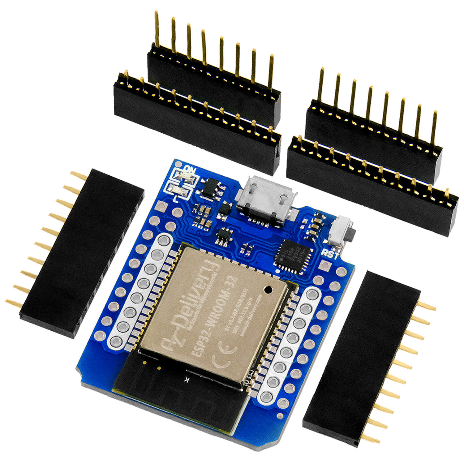
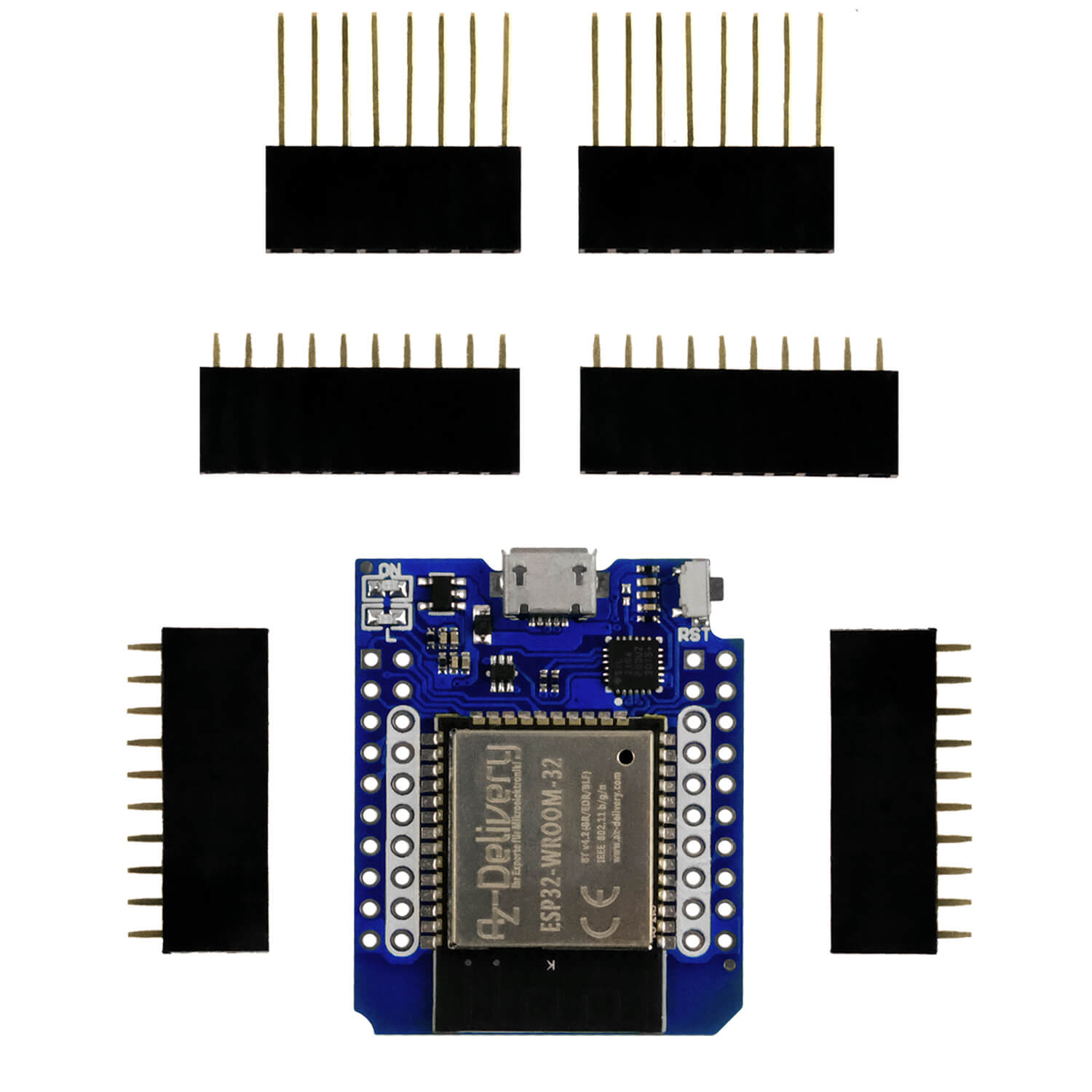
An ESP8266 D1 mini is very suitable due to its small dimensions. An 8-pixel or 12-pixel neopixel ring can be used for lighting. We place both on a breadboard. Of course, the use of an ESP32 or a Raspberry Pi Pico is also conceivable. There are no changes to the wiring or the program.
The hardware
I am using an ESP8266 D1 mini and a 12-pixel Neopixelring in this article.

Figure 1: Lamp hardware
The following connections must be made:
-
Ring Vcc to ESP8266 5V
-
Ring GND to ESP8266 GND
-
Ring In to D5 = ESP8266 GPIO14
The software
For flashing and programming the ESP32:
Thonny or
Signal tracking:
Firmware used for an ESP32:
The MicroPython programs for the project:
angel_light.py first demo program
soft_angel.py Operating program for the Christmas lights
MicroPython - Language - Modules and programs
You can find detailed instructionsfor installing Thonny here . There is also a description of how to burn the Micropython firmware (as of 18.06.2022) onto the ESP chip . How to get the Raspberry Pi Pico ready for use can be found here.
MicroPython is an interpreter language. The main difference to the Arduino IDE, where you always and only flash entire programs, is that you only have to flash the MicroPython firmware once at the beginning on the ESP32 so that the controller understands MicroPython instructions. You can use Thonny, µPyCraft or esptool.py for this. I have describedthe process for Thonny here.
As soon as the firmware is flashed, you can have a casual conversation with your controller, test individual commands and see the response immediately without having to compile and transfer an entire program first. This is exactly what bothers me about the Arduino IDE. You simply save an enormous amount of time if you can test simple syntax and hardware tests and even try out and refine functions and entire program parts via the command line before you knit a program from it. I also like to create small test programs for this purpose. As a kind of macro, they summarize recurring commands. Entire applications are then sometimes developed from such program fragments.
Autostart
If you want the program to start automatically when the controller is switched on, copy the program text into a newly created blank file. Save this file under main.py in the workspace and upload it to the ESP chip. The program will start automatically the next time the controller is reset or switched on.
Testing programs
Programs are started manually from the current editor window in the Thonny IDE using the F5 key. This is quicker than clicking on the Start button or using the Runmenu . Only the modules used in the program must be in the flash of the ESP32.
Want to use Arduino IDE again in between?
If you want to use the controller together with the Arduino IDE again later, simply flash the program in the usual way. However, the ESP32/ESP8266 will then have forgotten that it ever spoke MicroPython. Conversely, any Espressif chip that contains a compiled program from the Arduino IDE or the AT firmware or LUA or ... can easily be provided with the MicroPython firmware. The process is always as describedhere.
The Neopixel ring
Neopixel LEDs of type WS2812 contain three individual LEDs that emit red, green or blue light. They are controlled by a chip that receives its instructions via a type of bus system that is clocked at 800kHz by the ESP32/ESP8266.
With the I2C bus or the SPI bus, the signals from the controller, for example an ESP32, reach all the slaves on the bus in the same way and everyone sees everything. This is different with the WS2812 devices. Each module has a data input and a data output. Several blocks can be cascaded by connecting the data input of each additional block to the data output of its predecessor. The first module in the chain receives a pulse chain of three bytes for R, G and B from the ESP32, which it feeds itself, i.e. removes from the entire pulse train. All subsequent pulses are waved through and output at the data output. Each module in the chain takes its share in the same way and passes on the rest. This makes it possible to control each component in the chain individually. The intensity of each color can be varied in 256 steps, depending on the value of the byte received for the individual color. We specify the color code in the form of a list or a tuplewith three bytes for each WS2812.
Let's start with an experiment. We use the structure with the connections specified above. First, the Pin and NeoPixelclasses are imported. I create a GPIO pin object as an output and use it to instantiate a NeoPixel object with twelve devices. The NeoPixel instance neo contains a byte array buf and the method write(), with which the content of the byte array buf is transferred to the Neopixel ring. Inputs in REPL are formatted in bold, responses from the ESP8266 are shown in italics.
>>> from machine import Pin >>> from neopixel import NeoPixel >>> np=Pin(14,Pin.OUT) >>> neo=NeoPixel(np,12) >>> neo[0]=(0xe0,0x07,0x3c) >>> neo[1]=(0xf0,0xf0,0xf0) >>> neo.write() >>> neo.buf bytearray(b'\x07\xe0<\xf0\xf0\xf0\x00\x00\x00\x00\x00\x00\x00\x00\x00\x00\x00\x00\x00\x00\x00\x00\x00\x00\x00\x00\x00\x00\x00\x00\x00\x00\x00\x00\x00\x00') With neo[0], I address the first three elements of the array and pass the values for red, green and blue, 0xe0, 0x07 and 0x3c. Internally, this is done by the private function setitem(). The values are entered into the buffer in a different order. As we will see in a moment with the curve that I recorded with the help of the Logic Analyzer. The values are sent as they appear in the buffer. A 0 corresponds to a narrow pulse of approx. 500ns width followed by a pause of approx. 750ns. The 1 is sent by a pulse of 750ns and a pause of 500ns. It is noticeable that the first two bytes are sent in reversed order. This corresponds to the information from the data sheet and can also be verified as follows.
xxxxxxxxxxxx >>> neo.ORDER (1, 0, 2, 3) 
Figure 2: Pulse sequence for RGB = 0xE0, 0x07, 0x3C, 0xf0, 0xf0, 0xf0
The three bytes 0xe0, 0x07 and 0x3c, which this component has eaten, are missing at the output of the first WS2812B. Instead, the code 0xf0, 0xf0, 0xf0 comes out with a time delay, the code for the second module. For this measurement, the input for channel 1 of the logic analyzer was connected to the input of the first LED, channel 2 to its output.
Now we know how the kangaroo runs on the WS2812B and can turn to the program for the lamp later. But first, let's take a look at the angel that we want to light up.
The angel for the lamp
The lamp housing consists of a silhouette that is bent into a truncated cone.

Figure 3: Angel template finished
The template can be downloaded as PDF file. The black areas in Figure 2 are cut out with a cutter or, better still, a design knife. Once this is done, we roll up the paper, pin the wings together and glue the free back with the adhesive tab.

Figure 4: Cut out template

Figure 5: Angel in blue

Figure 6: Angel blue on red
The program
All beginning is not difficult
The first Demo program switches through the basic colors that we can achieve with the ring.
xxxxxxxxxxxx # angel_light.py # # Pin translator for ESP8266 boards # LUA-Pins D0 D1 D2 D3 D4 D5 D6 D7 D8 # ESP8266 Pins 16 5 4 0 2 14 12 13 15 # SC SD # used NE from machine import Pin from time import sleep import neopixel # Pin GPIO14 is connected to a 12-pixel neopixel ring n=neopixel.NeoPixel(Pin(14),12) rt =(255,0,0) gn =(0,255,0) bl =(0,0,255) ge =(255,255,0) cy =(0,255,255) pu =(255,0,255) ws =(255,255,255) sw =(0,0,0) colors =(rt,gn,bl,ge,cy,pu,ws,sw) for col in colors: color=col for i in range(12): # fill Buffer n[i] = color # Update the strip. n.write() sleep(3) We get the required modules on board and instantiate a Neopixel object on pin D5 = GPIO14. I have used a 12-ring here.
Then I define the tuples for the basic colors. In the outer loop, we run col through the elements of the tuple colors, which are the color codes just defined.
In the inner loop, we assign the color code to all buffer elements of the ring. We send the buffer content to the ring elements and wait three seconds in each case.
Soft transitions are more relaxing
Soft transitions are certainly more appropriate for the "staid time" than the staccato colors of the last little program. So let's get to work on smoothing out the lamp's behavior. The entries in colors are still the milestones. To create transitions, we introduce a few more variables. With steps we define the number of steps between the landmarks. Ideally, we choose a power of two for this. Larger values give us smoother transitions. From the number of steps, we calculate the step width step = 256 // steps. This always results in an integer. We store the dwell time for each color code in delay. steps and delay roughly define the period duration for an entire run at delay * steps milliseconds.
We always compare the components of the first color code with those of the following one. The last color code is followed by the code with the index 0 in the tuple colors. We therefore need a ring counter for addressing the codes. We construct this using the modulo operator. We use the number of color entries in colors as the divisor of an integer division. The modulo operator % returns the division remainder, which lies between 0 and len(colors) - 1.
The transition at the end of the tuple color is shown in the following example. Entries in REPL are formatted in bold, responses from ESP8266 are shown in italics.
xxxxxxxxxxxx >>> colors =(rt,ge,gn,cy,cy,bl,pu,pu,ws,sw) >>> len(colors) 10 >>> i = 8 >>> i += 1 >>> i 9 >>> i %= 10 >>> i 9 >>> i += 1 >>> i 10 >>> i %= 10 >>> i 0 The augmented assignments (augmented assignments) i += 1 and i %= 10 are short forms for i = i + 1 and i = i % 10.
In a loop in which j runs from 0 to steps - 1, we calculate the current values from the components of the two color codes col1 and col2. We need to distinguish between three cases.
a) The color components of the two codes are the same.
In this case, we transfer the component value to the current color code.
b) The component of the first code is smaller than the same component of the subsequent code.
In this case, we calculate the product value of the loop index j and the step size step and add it to the corresponding value of the component of the first color code col1.
c) The component of the first code is greater than the same component of the subsequent code.
In this case, we calculate the product value of the loop index j and the step size step and subtract it from the corresponding value of the component of the first color code col1.
Because the components are reassembled, we cannot use a tuple as a container; this data type is immutable. This means that the elements cannot be changed.
xxxxxxxxxxxx >>> color = (0,0,0) >>> color[1] = 255 Traceback (most recent call last): File "" , line 1, in module TypeError: 'tuple' object doesn't support item assignment Expanding a tuple with append() isalso not possible. >>> color = () >>> color () >>> color.append(255) Traceback (most recent call last): File " AttributeError: 'tuple' object has no attribute 'append' For these reasons, we have to use a listto assemble the current color code in color. The rest is now simple. In another for loop, we transfer the color code to the buffer of the Neopixel ring and send the buffer to the ring. Then we put the controller to sleep for delay milliseconds.
I still have two tricks up my sleeve.
Debugging:
During program development, it is often helpful to output the content of variables in REPL at neuralgic points, which is not necessary or even undesirable in the production phase. Ultimately, such outputs also influence the timing of the program. To avoid having to constantly insert and delete the print lines during debugging, we introduce the debugflag. The output should only take place if debug isTrue.
xxxxxxxxxx if debug: print(i,k,name1,name2) Clean program termination with Ctrl + C
If the program is interrupted with Ctrl + C at an unpredictable point, the LEDs continue to light up. Of course, we can then manually fill the buffer with (0,0,0) tuples each time and send it to the ring. It is more convenient if we intercept the keyboard interrupt with a try-except construction. Then we can have the LEDs switched off by the program, output a message and exit the program with exit().
Here is the entire program whose elements we have just discussed.
xxxxxxxxxx # soft_angel.py # # Pin translator for ESP8266 boards #LUA pins D0 D1 D2 D3 D4 D5 D6 D7 D8 RX TX #ESP8266 pins 16 5 4 0 2 14 12 13 15 3 1 # SC SD # Attention hi hi hi lo hi hi # used NE from machine import Pin from time import sleep_ms import neopixel from sys import exit # A 12-pixel neopixel ring is connected to pin GPIO14 noc = 12 n=neopixel.NeoPixel(Pin(14),noc) rt =(255,0,0) gn =(0,255,0) bl =(0,0,255) ge =(255,255,0) cy =(0,255,255) pu =(255,0,255) ws =(255,255,255) sw =(0,0,0) debug = False colors =(rt,ge,gn,cy,cy,bl,pu,pu,ws,sw) colnames = ("rt","ge","gn","cy","cy","bl","pu","pu","ws","sw") steps = 64 step = 256 // steps delay = 25 # ms while 1: try: for i in range(len(colors)): col1=colors[i] name1=colnames[i] k=i+1 k = k % len(colors) col2 = colors[k] name2=colnames[k] if debug: print(i,k,name1,name2) for j in range(steps): color=[0,0,0] for c in range(3): if col1[c] == col2[c]: color[c] = col1[c] elif col1[c] < col2[c]: color[c] = col1[c] + j * step else: color[c] = col1[c] - j * step if debug: print(color,col1,col2) for i in range(12): # fill Buffer n[i] = color # Update the strip. n.write() sleep_ms(delay) except KeyboardInterrupt: n.buf = bytearray( (0,0,0) * noc) n.write() print("Program aborted") exit() For autonomous operation, we must uploadthe program under the name main.py to the flash of the controller. The program will then start automatically at the next restart. Operation is possible either with a mains adapter or with the battery adapter and the Li-Ion cell. In the latter case, you can conveniently switch the setup on and off using the switch on the adapter.
Outlook
In the next episodes, we will transform the Christmas angel light into a year-round table lamp that can be controlled with sensor buttons. The ESP32, ESP8266 and Raspberry Pi Pico (W) will be used in different environments. There are also various tips and tricks for MicroPython.
Have a contemplative, staade time and see you soon!