DIY lighting with WLED: Programming an ESP light mixer
introduction
After the previous part 3 In the current post, we will use them in the current post to build a light control desired with an ESP32, on which the desired color can be easily mixed from the RGB shares. There is also an encoder for the effect. Thus, the previous software control is expanded to include an easy -to -use haptic control.
To get an overview of the set parameters, we use a small 0.96 “OLED display.
Hardware
You need hardware:
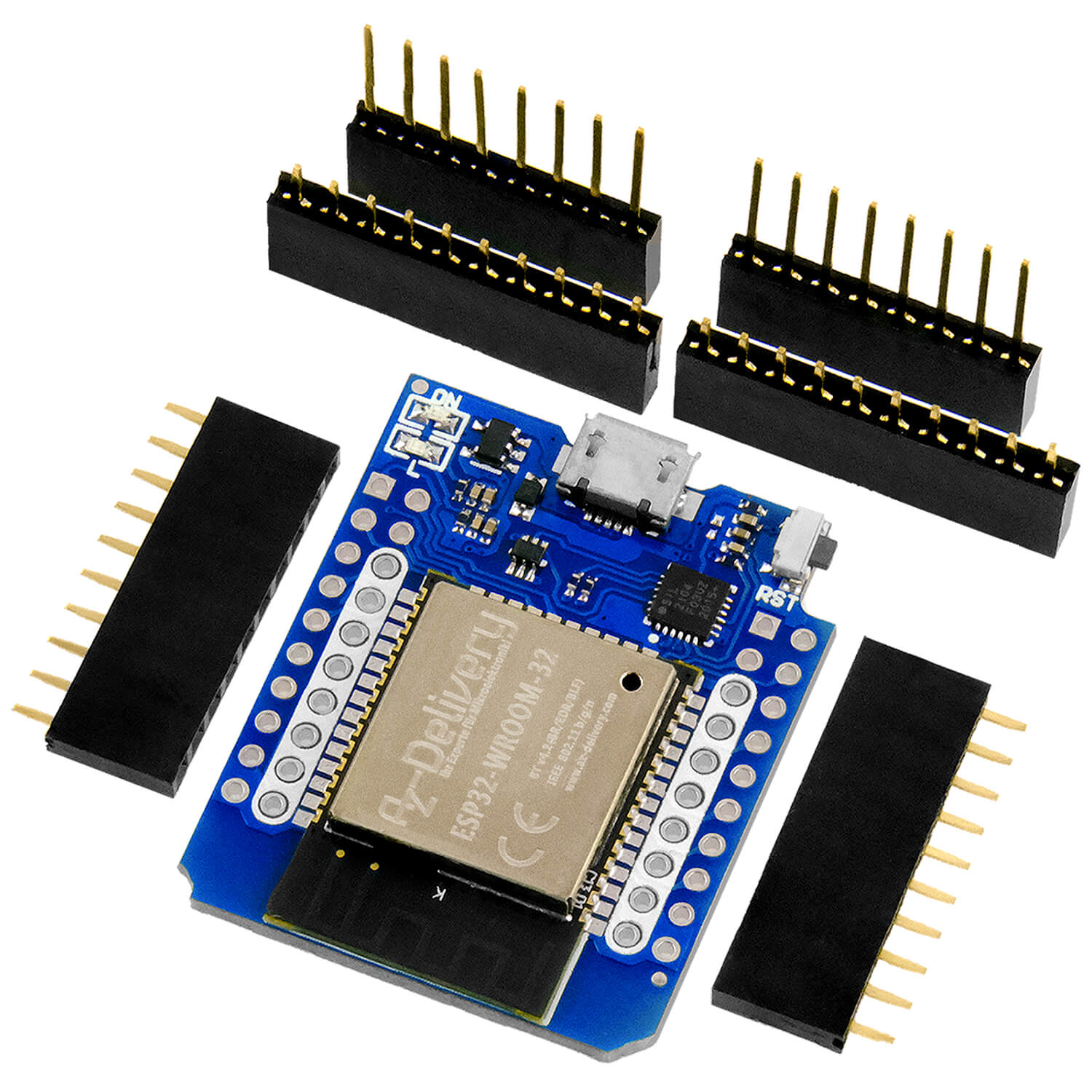
ESP32 board
5x Rotary
OLED display
Breadboard big
Breadboard small
Jumper cable
For the structure, you have to separate a power rail of the small Breadboard so that the distance is small enough to be able to stick the ESP32 on it. Next, cable the components as follows:
|
GPIO: |
Encoder PIN: |
|
|
27 |
CLK brightness |
|
|
26 |
Brightness dt |
|
|
14 |
Red CLK |
|
|
13 |
Red dt |
|
|
17 |
Green CLK |
|
|
16 |
Green dt |
|
|
19 |
Blue CLK |
|
|
18 |
Blue dt |
|
|
34 |
Effect CLK |
|
|
35 |
Effect dt |
|
GPIO: |
Display PIN: |
|
|
22 |
Scl |
|
|
21 |
Sda |
|

software
In the other parts (Part 1, Part 2, Part 3) we did without programming. This time we use a sketch that we load on the microcontroller via Arduino IDE.
If you program an ESP32 for the first time, copy the following link to Arduino IDE at: File-> Preferences-> Additional Boards Manager URLS: https://dl.espressif.com/dl/package_esp32_index.json
And install the ESP32 package in the board management.
The driver (CP2102) for this board should already be pre -installed by the operating system.
Install the following libraries:
'Adafruit GFX' and ,Adafruit SSD1306‘About the Library Manager in the Arduino IDE (Sketch> Include Library> Manage Libraries)
'ESP32encoder': Download the ZIP file from Github Down and install them in the Arduino IDE via Sketch> Include Library> Add .zip Library
Next, select the Board (ESP32 DEV Module) on the right COM port and load the following code to your board:
Download
This time you will find the explanations as comments in the source code
// integration of the librarys #include <Wire.h> #include <Adafruit_gfx.h> #include <Adafruit_ssd1306.h> #include <ESP32 code.h> #include <Wifi.h> #include <Httpclient.h> // Display configuration #define Screen_Width 128 #define Screen_height 64 Adafruit_ssd1306 display(Screen_Width, Screen_height, &Wire, -1); // WLAN access data const char* SSID = "SSID"; const char* password = "PSWRD"; // IP address of the WLED controller String WLED_IP = "192.168.xxx.xxx"; // Objects of the encoder class for every rotary code ESP32 code Brightness code, speech, green code, blue, effect; // Encoder pins #define Brightness_a 26 #define Brightness_b 27 #define Red_a 13 #define Red_b 14 #define Green_a 16 #define Green_b 17 #define Blue_a 18 #define Blue_b 19 #define Effect_a 35 #define Effect_b 34 // variables for WLED control intimately Brightness = 128; // brightness: 0-255 intimately red = 128; // red value: 0-255 intimately green = 128; // green value: 0-255 intimately blue = 128; // blue value: 0-255 intimately effect = 0; // Effect ID in WLED // array with effect name for display on the display const char* effectnames[] = { "Solid", "Blink", "Breathe", "Wipe", "Wipe Random", "Random Colors", "Sweep", "Dynamic", "Colorloop", "Rainbow", "Scan", "Dual Scan", "Fade", "Chase", "Chase Rainbow", "Running", "Saw", "Twinkle", "Dissolve", "Dissolve rnd", "Sparkle", "Dark Sparkle", "Sparkle+", "Strobe", "Strobe Rainbow", "Mega Strobe ", "Blink Rainbow", "Android", "Chase", "Chase Random", "Chase Rainbow", "Chase flash", "Chase flash rnd", "Rainbow Runner", "Colorful", "Traffic Light", "Sweep Random", "Running 2", "Red & Blue","Stream", "Scanner", "Lighthouse", "Fireworks", "Rain", "Tetrix", "Fire Flicker", "Gradient", "Loading", "In out", "In in" ", "Out out", "Out in", "Circus", "Halloween", "Tri Chase", "Tri Wipe", "Tri fade", "Lightning", "ICU", "Multi Comet", "Dual Scanner", "Stream 2", "Oscillate", "Pride 2015", "Juggle", "Range", "Fire 2012", "Colorwaves", "BPM", "Fill Noise", "Noise 1", "Noise 2", "Noise 3", "Noise 4", "Colortwinkle", "Lake", "Meteor", "Smooth meteor", "Railway", "Ripple" }; // help variable at http communication problem Boolean Bred = 0; void update(); void Display Valuesonscreen(); void set up() { Serial.Begin(115200); // initialize display IF (!display.Begin(Ssd1306_switchcapvcc, 0x3c)) { Serial.print(F("Oled not found!")); while (true); } display.Clear display(); display.SettextSize(1); display.SettextColor(SSD1306_White); // set internal pullup resistances ESP32 code::Anternalweak pull resistor = putype::up; // initialize Rotary Encoder Brightness code.Attachhalfquad(Brightness_a, Brightness_b); speech.Attachhalfquad(Red_a, Red_b); green code.Attachhalfquad(Green_a, Green_b); blue.Attachhalfquad(Blue_a, Blue_b); effect.Attachhalfquad(Effect_a, Effect_b); // rely encoder for default values Brightness code.setcount(Brightness); speech.setcount(red); green code.setcount(green); blue.setcount(blue); effect.setcount(effect); // Mail WLAN connection Wifi.Begin(SSID, password); display.Clear display(); display.setcursor(0, 0); display.print("Connect to wifi:"); display.setcursor(0, 16); display.print(SSID); display.display(); while (Wifi.status() != Wl_connected) { delay(500); Serial.print("."); IF(Millis() > 30000) ESP.remaining start(); // If no connection is established after 30SEK then restart then } display.Clear display(); display.setcursor(0, 0); display.print("Wifi Connected!"); display.display(); delay(1000); } void loop() { // Read encoder values (constrain limits the value) Brightness = constrain(Brightness code.scuffle(), 0, 255); red = constrain(speech.scuffle(), 0, 255); green = constrain(green code.scuffle(), 0, 255); blue = constrain(blue.scuffle(), 0, 255); effect = constrain(effect.scuffle(), 0, 80); // WLED supports effects up to ID 80 update(); Display Valuesonscreen(); delay(100); // demanding rate } // Function sends the HTTP requests to WLED void update() { IF (Wifi.status() == Wl_connected) { // check connection Httpclient http; // assemble the address from components String url = "http: //" + WLED_IP + "/Win"; url += "& A =" + String(Brightness); url += "& R =" + String(red); url += "& G =" + String(green); url += "& B =" + String(blue); url += "& Fx =" + String(effect); http.Begin(url); // initialize Request intimately httpcode = http.Get(); // Send Get-Request IF (httpcode > 0) { Serial.printf("WLED updated: %d \ n", httpcode); Bred = false; } Else { // Connection error Serial.printf("Error in WLED update: %s \ n", http.errorostring(httpcode).C_STR()); Bred = true; } http.end(); } } // function for displaying the values on the OLED display void Display Valuesonscreen() { display.Clear display(); display.setcursor(0, 0); display.SettextSize(1); // title display.print("Wled Control Panel"); IF(Bred) {// connection problem !! display.print("xxxxxxxxxxxxxxxx"); return; } Else { display.print("=================="); } // display brightness display.setcursor(0, 16); display.print("Brightness:"); display.print(Brightness); // Show red value display.setcursor(0, 24); display.print("Red:"); display.print(red); // Show green value display.setcursor(0, 32); display.print("Green:"); display.print(green); // Show blue value display.setcursor(0, 40); display.print("Blue:"); display.print(blue); // Show effect display.setcursor(0, 48); display.print("Effect:"); display.print(effectnames[effect]); display.display(); }
Conclusion

With the new light controller, colors can be easily mixed and effects can be played. In order to obtain even more flexibility, another encoder could be added to adjust the effect speed (& sx =). But sliding potentiometers can also be used instead of the encoder to mix the parameters more smoothly. You can also insert the Breadboard structure in a 3D printed housing.

Here the potentiometer is connected as a voltage divider so that the voltage can be easily tapped over the grinding contact. In the program the encoder.getcount () Command by Analogread (PIN) be replaced.
If a faster reaction to the set parameters is desired, it is advisable to look at the control UDP to throw (WLED Doc).
There are no limits to your own creativity.
If you do not see a video at this point, please change the cookie settings of your internet browser
Have fun recovery :)


