This post is also available as PDF document for download.
Welcome to a new episode of
Micropython on the ESP32 and ESP8266
today
The radio alarm clock contacts the cell phone
Our RC5 alarm clock does not have any controls, it doesn't need them either, because today we will address it with an app that runs on an Android cell phone or tablet. In this way, the layout of the control panel can be changed at any time, or adapted to personal wishes without having to fuselage on a housing. Because the functions of the Weckers are software-defined, the same applies to the circuit itself. The Parser can easily be installed further commands that can implement additional switching activities using added routines. The use of sensors in our SDAC (software defined alarm clock) is also conceivable, the measurement data of which can be passed on from the ESP32 to the cell phone. Here is a small summary of what has been dealt with as part of the project.
In the first episode we taught the ESP32 to read out RC5-IR remote control. In the second post the controller sends RC5-IR code itself. Then learned the ESP32how he can query a PS/2 keyboard. The ESP32 received an RTC with good accuracy in one further sequence donated after the on -board Real Time Clock (RTC) runs anything but exactly. A large 7-segment LED display came in Episode 5 in addition. Then we took care of one DCF77 module for contact with the PTB's time sign (physically technical federal institution). Finally we have the individual program parts for Furniture merged. A parser can implement the received commands into actions.
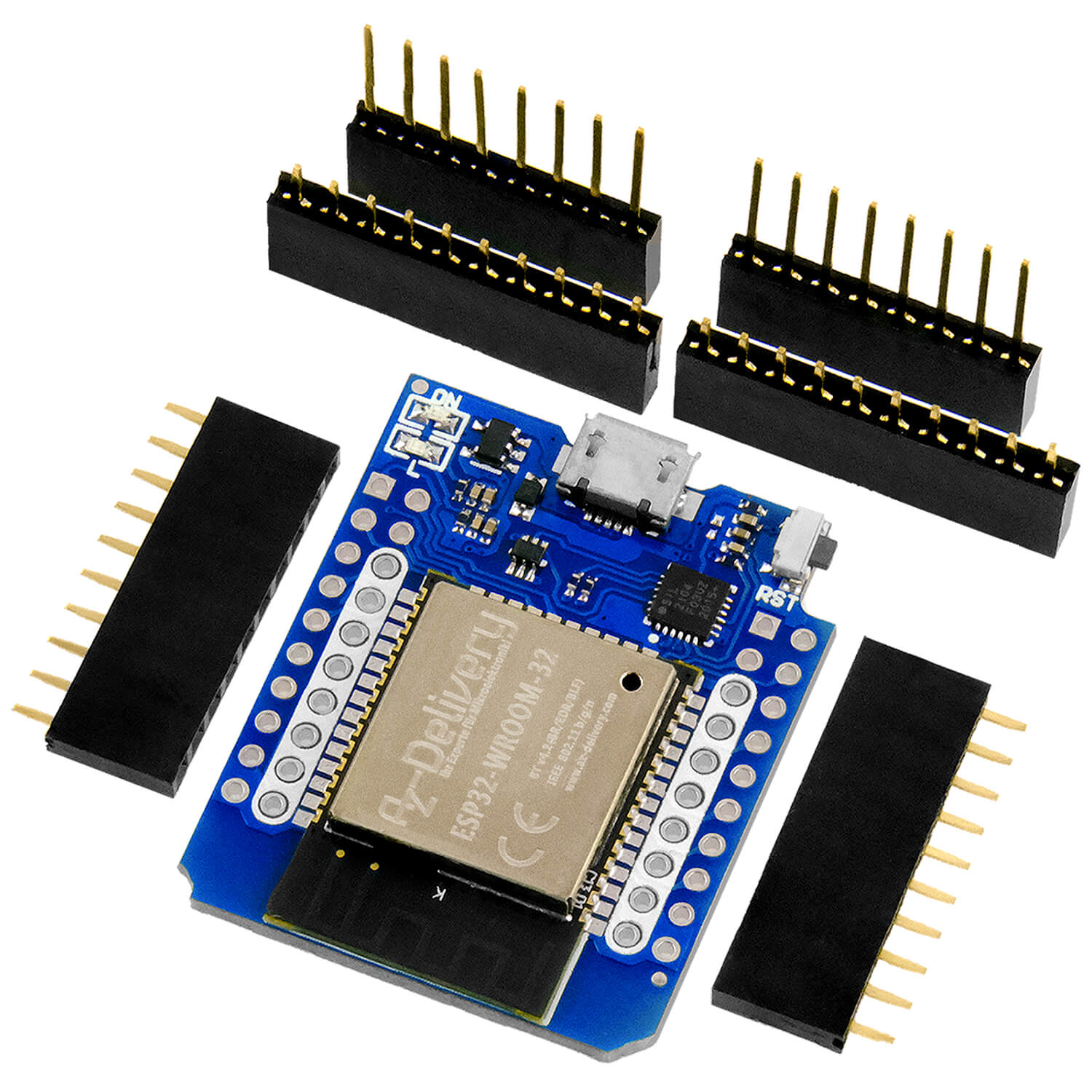
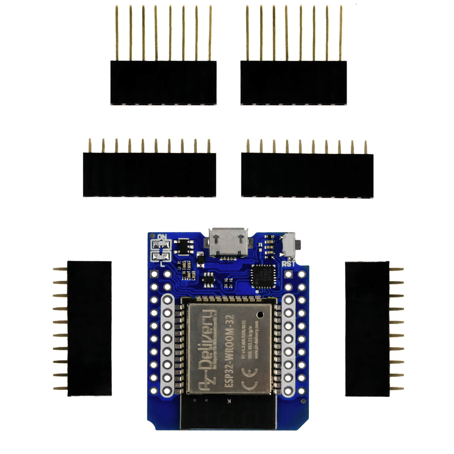
Below you will find the listing of the hardware and software. The description of the individual parts can be found in the blog posts above.
Hardware
Since no other parts have been added to the hardware, I took over the list from the last episode.
|
1 |
|
|
1 |
|
|
1 |
|
|
1 |
0.91 inch OLED I2C display 128 x 32 pixels |
|
1 |
|
|
1 |
|
|
various |
|
|
1 |
|
|
1 |
|
|
1 |
Ky-018 Photo LDR resistance Photo resistor sensor |
|
1 |
|
|
2 |
NPN transistor BC337 or similar |
|
1 |
Resistance 1.0 kΩ |
|
1 |
Resistance 10 kΩ |
|
1 |
Resistance 330 Ω |
|
1 |
Resistance 47Ω |
|
1 |
Resistance 560Ω |
|
1 |
LED (color at will) |
|
1 |
Adapter PS/2 according to USB or PS/2 socket |
|
1 |
|
|
1 |
PS/2 keyboard |
Figure 1 shows the circuit with all parts:

Figure 1: Everything together = radio clock with IR-RC ambitions

Figure 2: DCF77 reception module on ESP32
The software
For flashing and the programming of the ESP32:
Thonny or
Logic 2 operating software From Saleae
Packet station.exe: Network terminal for TCP and UDP
For the cell phone
AI2 company from the Google Play Store.
For the cell phone app
http://ai2.appinventor.mit.edu
https://ullisroboterseite.de/android-AI2-UDP/UrsAI2UDP.zip
With app_inventor_2_ger.pdf Instructions for the AI2 and the extension of Ullis robot side
Used firmware for the ESP32:
Used firmware for the ESP8266:
The micropython programs for the project:
tm1637_4.py: API for the 4- and 6-digit 7-segment display with the TM1637
ds3231.py: Driver module for the RTC module
oled.py: OLED-API
SSD1306.PY: OLED hardware driver
Buttons.py: Module for key query
dcf77.py: Driver for the DCF77 module
ir_rx.zip: Package for the IR reception module
irsend.py: IR broadcast module
timeout.py: Software -timer
sync_it.py: Synchronizing program with DCF77
second alarm.py: Trigger demo program to the alarm
Lern.py: Reading RC5 codes
Micropython - Language - Modules and Programs
To install Thonny you will find one here Detailed instructions (English version). There is also a description of how that Micropython firmware (As of 18.06.2022) on the ESP chip burned becomes.
Micropython is an interpreter language. The main difference to the Arduino IDE, where you always flash entire programs, is that you only have to flash the Micropython firmware once on the ESP32 so that the controller understands micropython instructions. You can use Thonny, µpycraft or ESPTOOL.PY. For Thonny I have the process here described.
As soon as the firmware has flashed, you can easily talk to your controller in a dialogue, test individual commands and see the answer immediately without having to compile and transmit an entire program beforehand. That is exactly what bothers me on the Arduino IDE. You simply save an enormous time if you can check simple tests of the syntax and hardware to trying out and refining functions and entire program parts via the command line before knitting a program from it. For this purpose, I always like to create small test programs. As a kind of macro, they summarize recurring commands. Whole applications then develop from such program fragments.
Autostart
If the program is to start autonomously by switching on the controller, copy the program text into a newly created blank tile. Save this file under boot.py in WorkSpace and upload it to the ESP chip. The program starts automatically the next time the reset or switching on.
Test programs
Programs from the current editor window in the Thonny-IDE are started manually via the F5 button. This can be done faster than the mouse click on the start button, or via the menu run. Only the modules used in the program must be in the flash of the ESP32.
In between, Arduino id again?
Should you later use the controller together with the Arduino IDE, just flash the program in the usual way. However, the ESP32/ESP8266 then forgot that it has ever spoken Micropython. Conversely, any espressif chip that contains a compiled program from the Arduino IDE or AT-Firmware or Lua or ... can be easily provided with the micropython firmware. The process is always like here described.
We build the app
The one with app inventory 2
AI2 is a free application of the with (Massachusetts Institute of Technology) that runs in the browser. The word 'building' aptly describes the process of app development. After the graphical surface of the app in the AI2-Designer is created, it goes in the window Blocks To stack together program modules, the blocks.
At this point, the AI2 Companion should already run on the cell phone so that you can follow everything that happens live on the cell phone in the app inventory. Start the app and click on the menu bar in Inventor window Connect - Ai Companion. The cell phone connects to the PC via the QR code. A local WLAN is required for this.
Start a browser, Firefox, Chrome, Opera ... There you place the app interface with the tools from the left column that palette, together. The elements are simply in the Viewer, the medium window, pulled and set off at the target position. In Components Then appear the preliminary identifiers of the objects, which they best replace with "speaking" names, that goes over the button Rename. I came up with a system for this that reveals both the type and the task of the objects. This later makes it easier to find and assign when assembling the program. Three small letters mark the type. The first letter of the subsequent name is very important.
In the Graves-Colte can be set the properties of the objects. Since I have often created apps for my projects and not want to include almost 20 pages of basic instructions in the post office every time, I have all of this in the blog post Working with the with app inventor 2 Or the document With app_inventor_2_ger.pdf packed in. There you will find out how to work with AI2, where you get the app AI2 company for the cell phone and UDP extension of Ullis robot page. If you haven't made anything with the AI2 yet, I urgently suggest you to read through this guide.
The graphic surface

Figure 3: App interface
We are now going through the individual elements of the design and start with the Screen1. This is the container in which all other ingredients will end up. I do not list properties, properties that are not changed. We change the background color. After clicking on the color field at Backgroundcolor Let's choose Custom and set the color.

Figure 4: Change background color

Figure 5: Set background color
The alignment of elements on the screen regulate these two fields:

Figure 6: Equipment of elements
The content of the screen becomes quite extensive. So that we can get to all elements, we do the umbrella Scrollable.
Figure 7: Allow rollers
The text in Title is displayed as an application name and under Rc5_control the app is saved in AI2.

Figure 8: Application name
In order to be able to group elements, we use so -called arrangements that we find in the layout folder.

Figure 9: Sub-container
We move in Horizontal arrangement in the viewer, baptize it harreceiving And make it invisible. However, so that it is displayed in the viewer, we will use there Display Hidden Components in Viewer a catch.

Figure 10: The first elements

Figure 11: View invisible elements in the view
We fill the horizontal arrangement with two labels from the user interface folder, LBLResponse and Lblanwer.
LBLResponse has the following properties:

Figure 12: Properties of LBLResponse
Lblanwer has the Text Left: 0, and receives as text "-".
The horizontal arrangement Harudpstate also contains two labels. Whose properties are, with the exception of the text, the same as at Lblanwer.
Now follows a vertical arrangement, Varipconfig, to which we implant two horizontal arrangements, Harlocalad dress and Harremotead dress.
Varipconfig:
Backgroundcolor: Custom (#c66c21ff)

Figure 13: Dialogue of the connection data
Harlocalad dress is fed with the following elements, the default values of which have been adjusted as follows:
Label LBLOCALADDR:
Fontsize: 14
Width: 70 pixels
Text: Local \ nip-Addr.
Textalignment: Right: 2
Text field txtlocalip:
Fontsize: 14
Width: 90 pixels
Text: 10.0.1.65
Textalignment: Center: 1
Label Label7:
Fontsize: 14
Text: ":"
Textalignment: Center: 1
Text field Txtlocalport:
Fontsize: 14
Width: 60 pixels
Text: 9091
Textalignment: Center: 1
Numbersonly: yes
Button btntakelkal:
Fontsize: 16
Text: OK
Harremotead dress is also structured but also contains the additional label Gothit.
The label LBlheadline Start the RC5 block.
Fontbold: Yes
Fontsize: 18
Width: Fill Parent ...
Text: RC5 controller
Textalignment: Center: 1
The key field of the RC5 control lives in a vertical arrangement. It consists of the sequence of the Off-Buttons that follow three horizontal arrangements, each contain three digits. The 0 button stands alone on the further hallway, followed by the horizontal arrangement with the keys for volume control. Between the controls, "nameless" labels are inserted to move the buttons apart. The same applies to the horizontal arrangements.

Figure 14: Arrangement of the keys
Varkeypad:
Allignhorizontal: Center: 3
AllignVertical: Center: 2
Width: Fill Parent ...
Backgroundcolor: Custom (#c66c21ff)
btnoff:
Backgroundcolor: Orange
Fontbold: Yes
Fontsize: 30
Height: 55
Text: off
Shape: oval
btn7: (representative of all other keys)
Backgroundcolor: Orange
Fontbold: Yes
Fontsize: 30
Height: Automatic
Width: 50
Text: 7
Shape: Rounded
Textalignment: Center: 1
The label LBlalarm settings is the heading of the alarm clock. The properties correspond to those of LBlheadline
The vertical arrangement varalar serves to control the alarm period.
The indication of the alarm period happens via the text field Txtalarmime. With the button SET the tax text is sent to the ESP32. Off Switch the alarm out of focus. Cancel alarm Switch off the alarm, but without deactivating it.
varalar:
Allignhorizontal: Center: 3
AllignVertical: Center: 2
Height: 150 pixels ...
Backgroundcolor: Custom (#c66c21ff)
This includes the horizontal arrangement Haralarm And the button btncancel alarm:
Height: 50 pixels ...
Backgroundcolor: Orange
Fontbold: Yes
Text: Cancel Alarm
Fontsize: 24
Texallignment: Center 1
Shape: oval
Haralarm:
Allignhorizontal: Left 1
AllignVertical: Top 1
In it are packaged:
BtNalarmoff / BtNalarmet
Height: 50 pixels ...
Backgroundcolor: Red /Green
Fontbold: Yes
Text: Off / Set
Fontsize: 30
Texallignment: Center 1
Shape: oval
Txtalarmime:
Height: 50 pixels ...
Text: 2:35
Fontsize: 30
Texallignment: Center 1
Hint: Wake -up time
Finally, we need a timer and the extension of Ullis robot side. The timer Clock1 Let's get from the Sensor folder. How to set up the extension can be found in the one recommended at the beginning Tutorial. Those in the folder Extensions The UDP blocks are the last to move to the viewer. The timer and the UDP blocks are invisible elements. They do not appear on the cell phone display. They still appear in the viewer, but below the cell phone image.
The program
Now it's time for us Packet station.exe Start on the PC. This enables us to follow the actions triggered by our app. For this reason, we also state the IP of the PC for the remote IP address. So the app does not send to the ESP32, but first to the PC with a packaging transmitter as a recipient. If everything is transmitted as desired, we switch the IP to the ESP32.

Figure 15: packaging transmitter - start window
About the File-Menu we call the Settings on to adapt the port address of packaging transmitters.

Figure 16: Set UDP port address
We are now switching to the folder in the AI2 window Blocks, we click on the button Blocks On the far right in the green title line.
As in micropython, we start declaring the global variables.

Figure 17: Variable declaration
From the folder Blocks.built-in we pull Initialize global-Blocks in the viewer.

Figure 18: Building blocks for working with variables

Figure 19: docking
We give a name for the variable and get out Blocks.built-in.text A block for a text constant and enter the text "00:00". Then we dock the text block to the variable block.

Figure 20: Take string variables
For numerical values we find the correspondence in Blocks.built-in.math.

Figure 21: Define numerical constants
We ask the IP address of the cell phone about the property Udpxmitter1.localhost away. We find them in Blocks.udpxmitter1.

Figure 22: UDP XMitter Property
Programs created with the AI2 are event-controlled, like our Micropython alarm program. So a main loop is running that is just waiting for a certain event to occur and then react to it.
The first event is the screen structure. In it we pack everything that is necessary to initialize our program. This is comparable to the preparations in Micropython, or the Setup ()-Block in the Arduino environment.
So what to do?

Figure 23: Initialization of the application
To set up a functioning UDP connection, we stop the recipient so that we can configure the UDP socket. Android takes care of the WLAN connection, we don't have to do anything.
You can see where you get the blocks from the block names. Control elements are beige, properties green, references on variable orange, logic elements light green and text elements pink. You can get another orientation through the color boxes in Blocks.built-in.
First of all, we feed the socket with the remote data and show the IP and the port number of our text fields Harremotead dress to. Then we start the socket again with the one we awarded Local sports number. Then we fill the text attributes of the fields in Harlocalad dress, put the timer on 1000ms and start it. The corresponding ISR will check and report the condition of the UDP connection.

Figure 24: Timer-ISR
When clock1.imer is called when the timer has expired. We delete the text in LBludpspragn And prove the attribute depending on the condition of the UDP socket. Then we start the timer again.
The local connection data in Harlocalad dress are taken over when the button btntakelkal is typed.
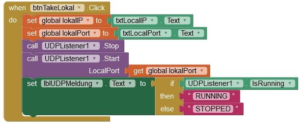
Figure 25: Take over local connection data
The global variables get the new values, the socket is stopped and restarted with the local port number. About the label LBludP report Let us find out the condition of the UDP interface. A click on the button works similarly btntakeremote For the remote data.

Figure 26: Apply remote connection data
UDP connection errors that occur can be found When udplisterer1. listenerfailure intercept.

Figure 27: Reaction to UDP connection error
We get the reference to the error code from the list Error code.
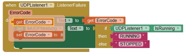
Figure 28: The reference to Errorcode
All buttons in Varkeypad Work on the same principle. When tapping, you have to send the message to the ESP32, which we are in the program alarm clock.py in the function parse() have determined from line 157.

Figure 29: Reaction to button clicks
In contrast to the establishment of the app interface in the designer, we can work with Copy & Paste to program the necessary events. The context menu calls for a right click on the block in question. Duplicate Creates a copy of the block, in which we only have to change the button object and the text to be transmitted. We choose the button object from the list that we get by clicking on the small, downward triangle. In this way we also create the treatment routines for the buttons BtNalarmoff and btncancel alarm.

Figure 30: Copy blocks
The following table establishes the connection between button designer and the transmission text.

Figure 31: Correlation button on message
For the button BtNalarmoff Let's add another addition. This puts the background color on light red when the alarm is deactivated.

Figure 32: Deactivate the alarm - supplement
Now we only lack the setting of the alarm period.

Figure 33: Set alarm period
Pressing the button should first be hidden the keyboard, which appears with the tapping of the input field. As a sign of setting an alarm period, the background color of the text field is set to light green. The global variable alarm Take over the value of txtalarmime.text. An empty input field is intercepted and the global variable alarm set to "00:00". Non -empty entries are first examined for a colon. If one is found, we replace the colon (normal separator in times) with a comma (syntactic separator of our news). alarm Is now on alarm set and finally with the command ALARM sent to the ESP32. Because we use the colon as a separator between the command and date part, we had to replace it at the top so that there is no confusion when parsing the ESP32.
If the correct messages appear in packaging transmitters when a button is typed on the cell phone and if the alarm period is transmitted correctly, then they have won.
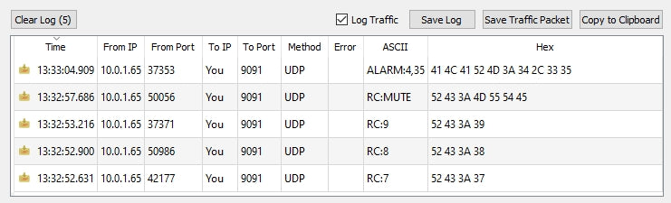
Figure 34: Reception from the cell phone app
Now the only thing left to change the IP address so that the cell phone messages are not sent to the PC, but to the ESP32. He should now react to the commands. Now is the right time to convert the ESP32 from the router to your own access point. All IP addresses are to be changed appropriately.

Figure 35: changed IP address
In order for the app to work regardless of the AI company, we have to compile it. This happens via the menu item Build.android app (APK).

Figure 36: Compiling the app
You can install the APK file in two ways on your cell phone: download or via the PC. You can read how this works in detail here or Here from page 16.
The complete APK file You can also find it as a download, also the Sourcethat you via Projects.import Project (.aia) from my computer can import in the AI2 inventor.