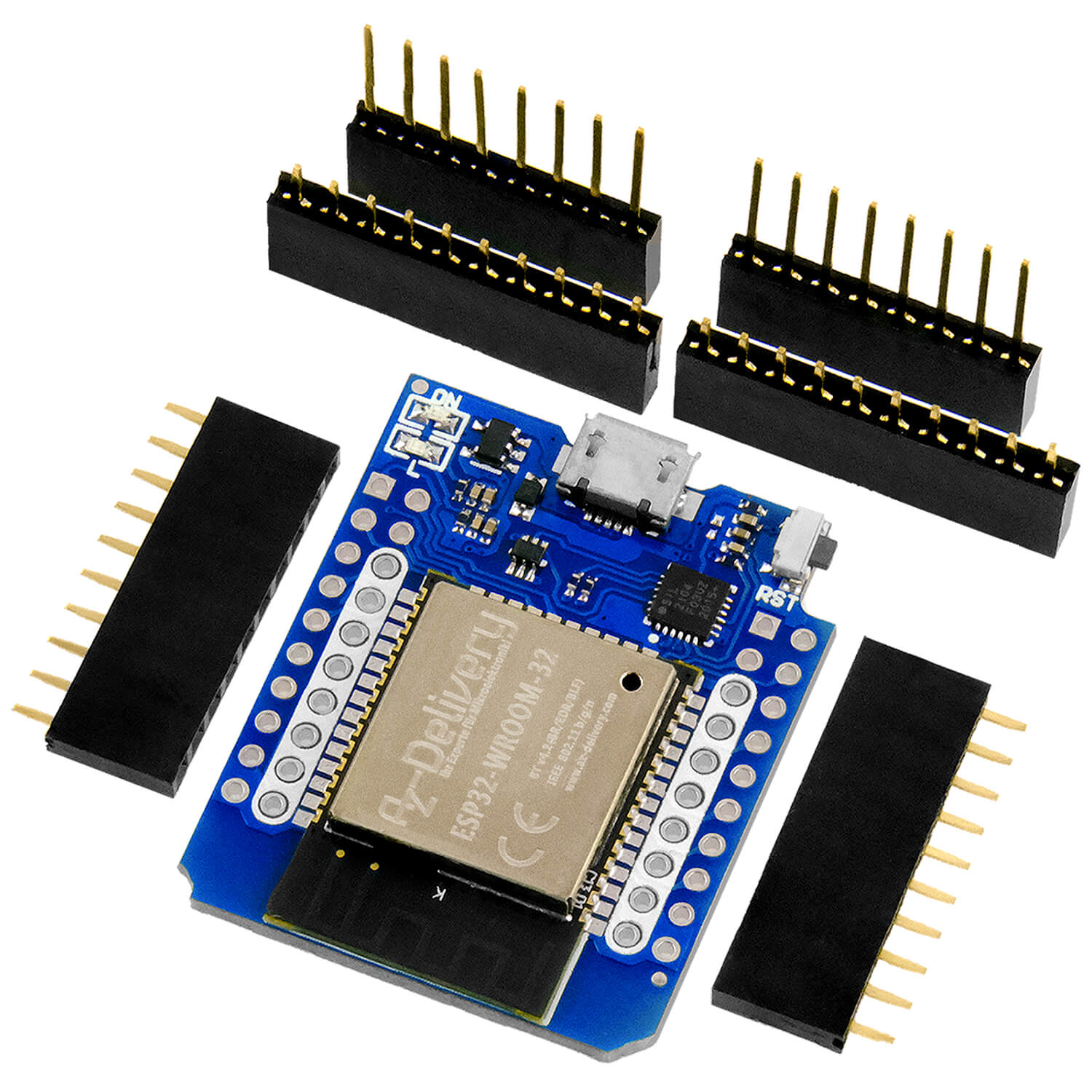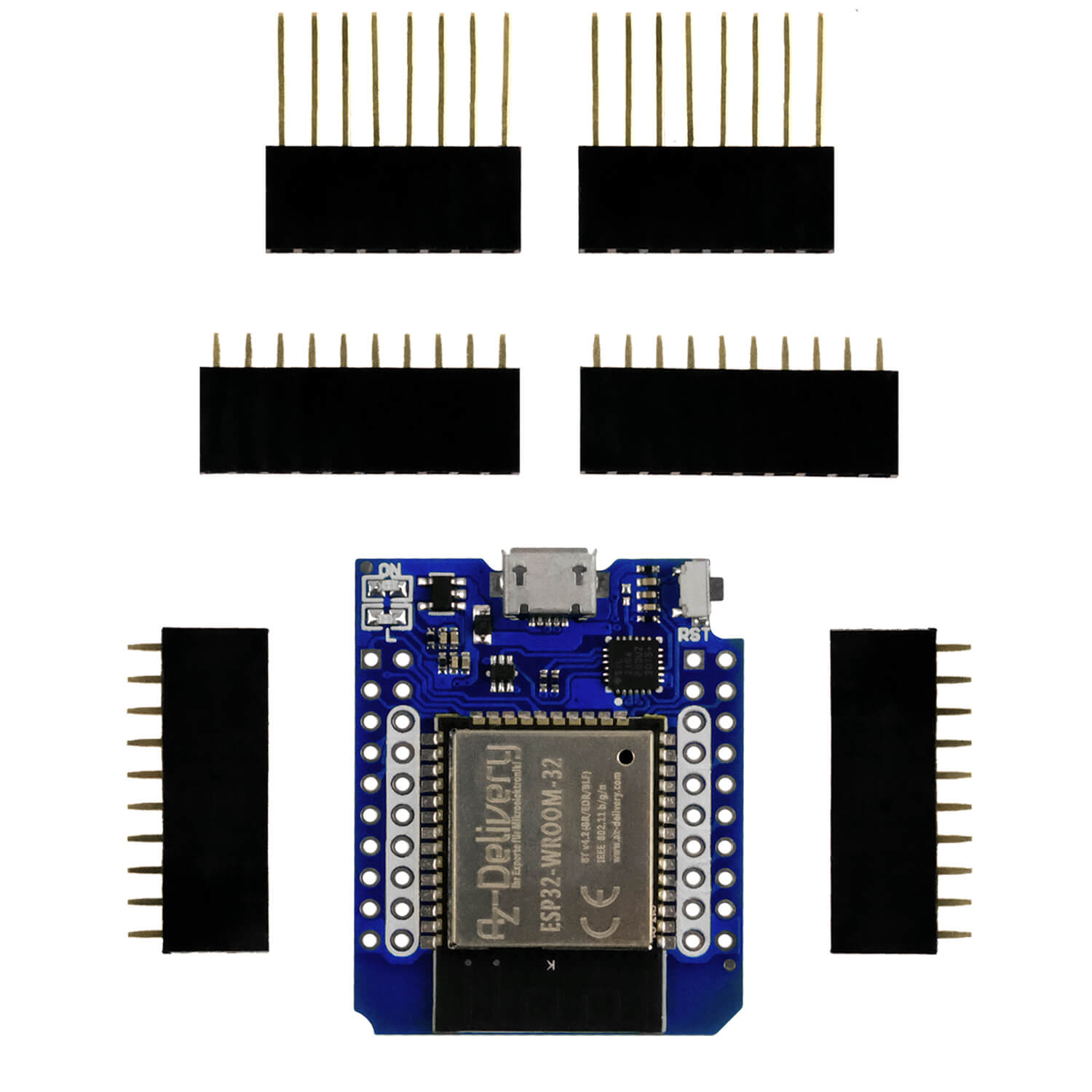
We have the Seeduino Xiao microcontroller in Part 1 of this series already configured and put into operation. It is time to use it with sensors. For these tests we will AZ-Delivery Use 16-in-1 sensor kit because it contains a very large variety of sensor types. We will build up some small and simple projects.

First we will connect each sensor of the kit individually to
Find out how we can program you with the Seeduino Xiao. Then we set up two mini projects.
A very important note before we start: The operating voltage of the Seeeduino Xiao pins is a maximum of 3.3 VDC. So we have to be particularly careful when we connect the sensor modules. If we create a supply voltage of 5 VDC to a module, the sensor data signal between 0 VDC and 5 VDC will work and with this voltage the sea eduino pin becomes unusable. It could even destroy the microcontroller itself.
If you are ready and have the 16-in-1 sensor kit together with the Seeduino Xiao microcontroller, we start with our first 8 sensors projects in the kit.
LED traffic

This module simulates a traffic light. The operating voltage is between 3.3 VDC and 5 VDC, so that we can connect it directly and without voltage restriction to the pins of our Seeeduino microcontroller. The test circuit is shown in the figure.
The sketch is very simple. We declare variables with the colors of the three LEDs and assign you the pin number to which you are connected. The pins are outputs. We program the LEDs in such a way that they turn on and off with a time delay. The red and the green LED remain and the yellow LED flashes four times. This module can be used for model railways, for example.
intimately red_led=0;
intimately yellow_led=1;
intimately green_led=2;

void set up() {
    pin mode(red_led, OUTPUT);
    pin mode(yellow_led, OUTPUT);
    pin mode(green_led, OUTPUT);

    digital(red_led, Low);
    digital(yellow_led, Low);
    digital(green_led, Low);
}

void loop() {

    digital(red_led, HIGH);
    delay(4000);
    digital(red_led, Low);
    delay(200);

    digital(yellow_led, HIGH);
    delay(500);
    digital(yellow_led, Low);
    delay(500);

    digital(yellow_led, HIGH);
    delay(500);
    digital(yellow_led, Low);
    delay(500);

    digital(yellow_led, HIGH);
    delay(500);
    digital(yellow_led, Low);
    delay(500);

    digital(yellow_led, HIGH);
    delay(500);
    digital(yellow_led, Low);
    delay(200);

    digital(green_led, HIGH);
    delay(4000);
    digital(green_led, Low);
    delay(200);
}
Ultrasonic sensor module HC-SR04

This sensor has an ultrasound transmitter and recipient. The transmitter sends out a wave that meets and reflect on an object. The recipient recognizes the reflected wave and the microcontroller measures the time that has passed between the broadcast and reception of the wave. He then carries out the necessary calculations to determine the distance to the recognized object.
We use the library SR04.Hto simplify the code. We only have to define variables to set the pins for sending and receiving the ultrasound signal and save the calculated removal, which is also displayed in the serial monitor. An example of the use of this sensor is in Project for Halloween 2022 to see.
/***** Required Libraries *****/
#include "SR04.H"

/***** Implementation of the Ultrasonic Sensors *****/
#define trig_pin 0
#define echo_pin 1
SR04 Ultrasonics_Sensor = SR04(echo_pin, trig_pin);
long spacer;

void set up() {
      Serial.Begin(9600);
}

void loop() {
      distance_object();
}

void distance_object() {
      spacer = ultrasonics_ensor.Spacer();
      Serial.print("Distance to Obstacles:");
      Serial.print(spacer);
      Serial.print("Cm");
      delay(100);
}
PIR sensor module

The passive infrared sensor is used to identify movements in a certain area. It is often used in toys, home automation or security systems, for example in the entrance area of a house.
All bodies release a certain amount of infrared energy, the greater the temperature of the body. These PIR sensors have sensors that collect the radiation and convert it into an electrical signal. These sensors make measurements from two different points and the electronic circuit compensates for the two measurements. If the two measuring points receive the same amount of energy, the difference is zero and there is no change in the output signal. If there is a difference between the measurements of the two points, a change in the output signal is created. In this way, the presence of an object can be determined based on the difference of the measured values.
If the sensor recognizes a movement, it changes "SIGNAL"-Pin his condition to inform the microcontroller that a movement has been recognized. The sensitivity and the time of changing the output signal status can be set. House alarm Project.
A notice: The design of these modules can vary. To ensure how the pins are arranged, remove the white cap. There they see the lettering of the pins.
#define Out_pin 2

uint8_t output_value = 0;
Bool motion_detected = false;

void set up() {
      Serial.Begin(9600);
      pin mode(Out_pin, Input);
      delay(60000);
}

void loop() {
      output_value = digital read(Out_pin);

      IF (output_value) {
            Serial.print("Object Detected!");
            motion_detected = true;
            delay(3000);
      } Else {
            Serial.print("No Object!");
      }

      IF (motion_detected) {
            Serial.print("Wait!");
            delay(6000);
            Serial.print("Ready ...");
            motion_detected = false;
      }
}
LDR sensor module (light-dependent resistance)

The LDR sensor module is a module with a resistance that changes its value depending on the incidence of light. The sensitivity level is regulated with the potentiometer on the module. This module can be used, for example, to turn on a lamp if the amount of the ambient light decreases. One example is the project Sunlight Tracker, in which light measurements with four LDRs and calculations are carried out in order to move a mechanical assembly with stepper motors so that a photovoltaic panel is brought into the optimal position for capturing the view. Cover the LDR resistance by hand so that it does not cover the light and you will see in the serial monitor how the messages change.
#define Do_pin 2

void set up() {
      Serial.Begin(9600);
      pin mode(Do_pin, Input);
}

void loop() {
      intimately lights = digital read(Do_pin);
      IF (light == HIGH) {
            Serial.print("The Light is not present");
      } Else {
            Serial.print("The Light is present");
      }
}
Ky-037 microphone module

The KY-037 microphone module has a passive microphone, an amplifier and an integrated circuit for comparing the noise level. The frequency range lies from 20Hz to 20kHz. With the potentiometer of the module, we set the reinforcement for noise recognition. It has an analog signal pin with which the noise level can be measured as a voltage, as well as a digital signal pin with which a high or low output level can be used. A possible application would be to switch the lighting on and off in a room by clapping in the hands. In the two sample sketches we see how the message on the serial monitor outputs the output of the digital pin and the signal on the serial plotter signal the analogue pin.
Digital PIN
const intimately mic =  2;

void set up() {
      Serial.Begin(9600);
      pin mode(mic, Input);
}

void loop() {
      IF (digital read(mic) == HIGH) {
            Serial.print("Hearing something");
      }
}

Analog-PIN
void set up() {
      Serial.Begin(9600);
}

void loop() {
      intimately sensorvalue = analogead(A2);
      Serial.print(sensorvalue);
}

Vibration sensor

This module has a digital output and consists of a capsule with two metal bars inside, one of which is fixed and a spring is attached to the other. This can react to sudden movements, bumps or vibrations.
intimately vibration_ensor = 1;
intimately Val;

void set up() {
      pin mode(vibration_ensor,Input);
      Serial.Begin(9600);
}

void loop() {

      Val=digital read(vibration_ensor);
      IF(Val==HIGH) {
            Serial.print("Detected vibration!");
      } Else {
            Serial.print(".......");
      }
}
Inclination sensor module

This module, like the previous one, also has a capsule, but in this case there is a metal ball inside, which sets the ball in motion and closes two metal contacts if there is sufficient inclination. The digital starting pin then changes its condition.
intimately tilt_sensor = 1;
intimately Val;

void set up() {
      pin mode(tilt_sensor,Input);
      Serial.Begin(9600);
}

void loop() {

      Val=digital read(tilt_sensor);

      IF(Val==HIGH) {
            Serial.print("HIGH!");
      } Else {
            Serial.print("Low!");
      }
}
Line success sensor

This sensor has an infrared transmitter and a recipient. He recognizes a line that is painted on the floor in black color on a preferably white background. Black color has the property of absorbing light. The outer light of the sensor module is not reflected back to the recipient. The white color, on the other hand, completely reflects the light. So the sensor can distinguish between black and white. The maximum distance in which the module can work is 15 mm. The sensitivity is set with the potentiometer of this module. With these properties, the sensor can be used, for example, in a toy car to automatically follow a line. You can find an example of this project in the article Line -based robot car.
intimately line_tracker_ensor = 1;
intimately Val;

void set up() {
      pin mode(line_tracker_ensor,Input);
      Serial.Begin(9600);
}

void loop() {
      IF(Val==HIGH) {
            Serial.print("HIGH!");
      } Else {
            Serial.print("Low!");
      }
}
Mini projects with modules from the AZ delivery program 16 in 1
We will now create two projects with some of the modules that I have just described. One of them will be a parking warning system, as most vehicles currently use and the other is a system for switching on the lighting when a movement is recognized or the ambient light is too dark.
Parking war

Nowadays, many vehicles have a parking warning system in which both an acoustic signal and light signals on the inner screen warn of obstacles. The system is very simple: a certain number of ultrasonic sensors, which are distributed on the front and rear bumper, detect the distance. When the vehicle begins the parking maneuver, the screen usually shows a drawing of the vehicle and some colored beams (usually green, yellow and red) in the outline of the vehicle, which tell us how far the object is away. Depending on the extent that an acoustic signal sounds, the more intense the vehicle approaches an obstacle.
In our mini project we use the ultrasonic sensor HC-SR04, the traffic light module and The passive summer module Ky-006that is not included in the 16 in 1 kit. The functionality of this circuit is very simple: If the object is more than 30 cm away, the LEDs do not light up and the buzzer does not sound. If we approach the object and the distance between 30 cm and 15 cm, the green LED lights up and the summer sounds with a frequency of 400 Hz. If the distance is between 15 cm and 5 cm, the yellow LED lights up, The green LED expires and the summer sounds with a frequency of 500 Hz. If the distance is reduced even further and and is only 5 cm or less, the red LED lights up, the two remain out and the Summer sounds with a frequency Of 600 Hz. The sketch is easy to understand and provided with explanatory comments. In this short video you can see how it works.
System of presence lighting

The following small project switches on the light when moving or if the outer light is too low. It can be used as an energy saving system.
For this circuit we will use the PIR module for motion detection and the LDR module for the detection of a low illuminance. We will use an LED diode to simulate the lighting.
The Signal PIN of the PIR sensor changes when a movement has been recognized. In this case, the microcontroller switches on the LED, otherwise it will be switched off.
The signal pin of the LDR module changes from low to high when the lighting becomes too low. Even then, the LED is switched on by the microcontroller.
This sketch is also commented on so that it is easy to understand. In the video you can see how it works.
If the videos are not displayed, please check the cookie settings of your browser!
We hope that you liked the analysis of these first 8 modules of the kit and that you can realize your projects with it. In the next part we will devote ourselves to the other sensor modules and implement some other mini projects.