This post is also available as PDF document for download.
I have already presented two types of electric motors in other blog episodes. at the Robot car It was normal DC engines that were controlled by PWM signals at the speed using the Motorshields. The servomotors during the game were also used by PWM signals Joyballwizzard controlled. I used the PCA9685 driver module there. But the Motorshield can do even more. The driver levels of the L293 installed on it can also drive university and bipolar stepper motors with a motor voltage in the range from 4.5V to 36V and a maximum current of 600mA. How this works and which design of stepper motors, aka stepper engines, there are, I will reveal this in this new episode of
Micropython on the ESP32 and ESP8266
today
Revolutions step by step step by step
In a normal electric motor, an anchor rotates with one or more offset windings in an outside magnetic field. The electricity is fed to the anchor windings via a commutator. This component automatically switches the different coil pairs through the coal brushes through the rotation of the anchor. With such a motor, however, you cannot approach a certain angle position, at least not without further aids, such as an angle code. The position of the anchor is not raster. It is not predictable in which angle position the anchor comes to a standstill.
If, conversely, a permanent magnet is placed in an external field of magnetic coils, which is switched on and off or switched off by a tax part in a very specific rhythm, then certain angles of the rotation can be targeted. With this design, however, the number of poles of the stator and thus the fineness of the angle division is limited. In Figure 1, the right coil is flowing through the current in such a way that a North Pole arises compared to the anchor. The anchor is held in this position. If you activate the lower coil next, the anchor makes a quarter turn in clockwise and so on. After four steps, the rotor turned 360 degrees.

Figure 1: Permanent magnet stepper engine
A different design uses a jagged Softwhose patches are attracted by the field magnet poles, which are also jagged. The rotor moves in such a way that its patches are contrasted with the patch of the stator pole as precisely as possible and thus allow a greatest possible magnetic river through the soft iron of the anchor. With this design (reluctance engine), a finer angle step width can be achieved. The term reluctance describes the magnetic resistance that the field lines have to overcome in the course. It is very large in air, in ferromagnetic fabrics such as iron, it is very small. When activating a statormary agencies, the rotor goes into a position in which the reluctance is minimized. This is the case if the jags of the stator and rotor are only separated by a narrow air gap.
However, because the rotor is made of soft iron, there is no holding moment in the electricity.

Figure 2: Reluctance step motor
The rotor in Figure 2 makes an angle step of 2 degrees when activating the next coil. This results in 180 steps per revolution. After four steps, four teeth of the rotor are again opposite those of the red coil.

Figure 3: Reluctance step motor - step sequence
Circuit of the coils
Regardless of the hardware design of a stepper motor, the coils can be switched differently and controlled.
Unipolar motors
In Figure 4 we have an unipolar motor. It is called that because the coils all only create a magnetic field of a orientation, they are only switched on and off.

Figure 4: Unipolarm motor
By closing and opening the switch A to D row, the rotor carries out four steps. Which angles result from the construction of the engine depends.
In real life, the switches are of course replaced by transistors that are controlled by a microcontroller. The controller specifies the clock and determines the direction of rotation of the motor-A-B-C-D-A-B ... in clockwise A-D-C-B-A-D… in the opposite of the control signals. The transistors only have to tolerate the motif and the coil current, the control is quite simple. To protect the transistor, a freewheel diode must be switched in parallel to the coil, which intercepts the voltage tips when the coil current is switched off.

Figure 5: transistor circuit for a coil
For the engines that I use (up to 15V and 300mA to 500mA), a BC337 (45V, 800mA) or a daring tone type, for example BC517 (30V, 1a), would be easy. However, because we will mainly use bipolar engines, we solve the control problem differently, more than that.
Bipolar engines
In this engine class, the coils are not only switched on and off, but also polished. To do this, you need four switches again. To switch off the left coil, the opening of switch A or D, the magnetic field of the coil is reversed if A and D are opened and B and C are closed. The situation is similar in the second winding.

Figure 6: Bipolarmotor
It becomes difficult when replacing the switches with transistors. For switch A, C, E and G at the hot end, i.e. against the positive pole, the control by a GPIO connection becomes more complex and complicated, especially with motor stresses of 5V and more. Without an additional preliminary stage, which raises the 0V to 3.3V at the controller output on the plus level of the motor voltage, nothing works.
I wanted to save myself the piping, so I chose the Motorshield with his two L293D chips. An L293D is an IC that provides two full bridges in the form of two separate half -bridges. In principle, a half bridge looks like the switch A and B shown above, only with transistors. We are looking at this exactly now.

Figure 7: Starting level (data sheet of the L293D)
How the lower and upper level is controlled does not have to be interested, it is only important that the two NPN end-step transistors can switch through and lock them separately and that this is controlled via two inputs that require the logic level up to five volts. This corresponds to closing and opening the switches. It is also important that every H bridge of the L293D is already secured with freewheel diodes. The L293 (without D) did not integrate these diodes on the chip. Therefore, you cannot easily replace an L293D with an L293.

Figure 8: L293 - power amplifier H -bridge - L293 (left) and L293D (right) (data sheet of the L293d)
The chip can switch motifs up to 36V up to 600mA for current strengths, and that with normal DC motors, unipolar and bipolar steps. For this, a further voltage VCC1 from 4.5V to 7V is required for the switching logic. It is important for us that the tax inputs already recognize a voltage of 2.3V as a logical 1 if we create 5V as a supply voltage. We could therefore easily operate a tax input of the L293D with a GPIO output of the ESP32 or ESP8266.
"Could" because on the one hand the two half -bridges have to be switched over at the same time and on the other hand, another chip is installed on the Motorshield, from which the half -bridges are ultimately controlled. But it is precisely this SN74HC595, a sliding register, that enables us to fulfill the first condition in a simple manner. An ESP cannot do this directly because we can only switch the GPIOs one after the other. Figure 9 shows a way out, but it uses an additional IC with inverters at the entrance.

Figure 9: L293 - Bipolar stepper motor control (data sheet of the L293d)
One disadvantage of this circuit is that the outputs always have different potential. None of the coils can therefore be switched without it.
Figure 10 also shows the connection of a bipolar stepper motor with coils L1 and L2 to the L293d.

Figure 10: L293 - Connection of a bipolar stepper motor (data sheet of the L293d)
In this case, we can have the entrances to Pins 2, 7, 10 and 15 ourselves. Pins 1 and 9 are enable inputs, which means that the half-bridges are activated when the pins are pulled to logical 1. These inputs are led separately on the Motorshield. The complete pin assignment of the ICS can be seen in Figure 11.

Figure 11: L293 - Pin occupancy (data sheet of the L293D)
The inputs 1a, 2a, 3a and 4a are controlled by the pins Qa (15), QG (6), QH (7) and QF (5) of the SN74HC595. That goes a little confused and probably has to do with the conductor management tour.

Figure 12: 74HC595 - Pin assignment (data sheet of the SN74HC595)
For the transfer of bytes to the sliefer, we need the inputs Ser (14), RCLK (12) and SRCLK (11). The data bits are placed on SER and taken over with the positive flank to SRCLK in 74HC595. With each clock, bits that have already been received are pushed on. Once all eight bits have arrived in the shistle, we all take a simultaneous take over with a pulse to RCLK (Ripple Clock) to the output flip-flops. -OE (output enable) we firmly put on GND potential and thus the corresponding logic levels also appear at the Q outputs and are also forwarded to the inputs of the two L293D. Each of the two can therefore operate a stepper motor. Figure 13 provides information about the inner life of the 74HC595.

Figure 13: Slide Register 74HC595 (data sheet of the SN74HC595)
Hardware
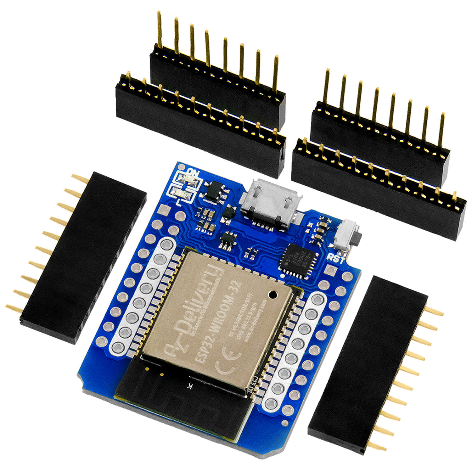
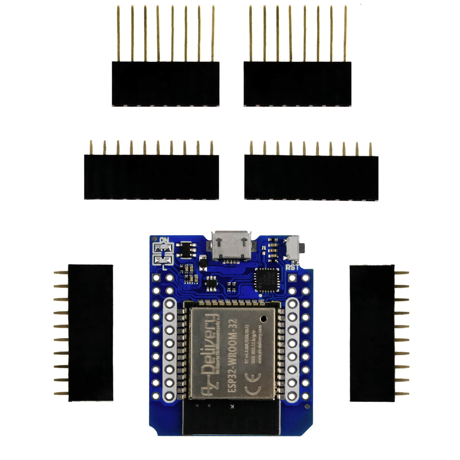
| 1 | ESP32 Dev Kit C unpleasant or ESP32 NODEMCU Module WiFi Development Board or Nodemcu-ESP-32S kit or Nodemcu Lua Amica Module V2 or ESP8266 ESP-01S WiFi WiFi module or D1 Mini V3 Nodemcu with ESP8266-12F |
|---|---|
| 1 | 4-channel L293D Motor Driver Shield |
| 1 | Breadboard Kit - 3x Jumper Wire M2M/F2M/F2F + 3 Set MB102 Breadbord Compatible with Arduino and Raspberry Pi - 1x Set |
| 1 | Stet engine uni or bipolar e.g. Pollin order no. 310689 or 310690 |
| various | Jumper cable |
| Optional | Logic Analyzer |
Let's put the parts together now. Figure 14 shows the circuit of the Motorshield. The positions of the connections to the individual ICS are important for us. The dashed lines lead to the left L293D, which we do not use. The enable lines of the right L293D are led to pins 5 and 6 on the Shield, which we create on +VCC1 +5V. -Oe of the Sn74HC595, at pin 7 of the board, we connect to GND.

Figure 14: Motorshield - Inner life and follow -up assignment
Ser, SRCLK and Latch = RCLK go to the ESP8266.

Figure 15: Motorshield on the ESP8266-Amica - Block circuit
Now only the engine is missing. You can see some copies in Figure 16. Those in the upper row, except for the far right, bipolar types of Pollin. The right is an unipolar engine from my smorgasbord. In the lower row there are engines that I have expanded from old printers or scanners.

Figure 16: Different stepper motors
And so the engine is connected to the Shield:

Figure 17: Stepper engine - circuit

Figure 18: Step motor on Motorshield
After discussing the hardware foundations, we are now turning to programming.
The software
For flashing and the programming of the ESP32:
Thonny or
pack box To test the ESP8266 as a UDP client and server
Saleae – Logic analyzer software (64 bit) For Windows 8, 10, 11
Used firmware for an ESP32:
Used firmware for an ESP8266:
The micropython programs for the project:
shieldtest.py Operating program
Micropython - Language - Modules and Programs
To install Thonny you will find one here Detailed instructions (English version). There is also a description of how that Micropython firmware (As of 05.02.2022) on the ESP chip burned becomes.
Micropython is an interpreter language. The main difference to the Arduino IDE, where you always flash entire programs, is that you only have to flash the Micropython firmware once on the ESP32 so that the controller understands micropython instructions. You can use Thonny, µpycraft or ESPTOOL.PY. For Thonny I have the process here described.
As soon as the firmware has flashed, you can easily talk to your controller in a dialogue, test individual commands and see the answer immediately without having to compile and transmit an entire program beforehand. That is exactly what bothers me on the Arduino IDE. You simply save an enormous time if you can check simple tests of the syntax and hardware to trying out and refining functions and entire program parts via the command line before knitting a program from it. For this purpose, I always like to create small test programs. As a kind of macro, they summarize recurring commands. Whole applications then develop from such program fragments.
Autostart
If the program is to start autonomously by switching on the controller, copy the program text into a newly created blank tile. Save this file under boot.py in WorkSpace and upload it to the ESP chip. The program starts automatically the next time the reset or switching on.
Test programs
Programs from the current editor window in the Thonny-IDE are started manually via the F5 button. This can be done faster than the mouse click on the start button, or via the menu run. Only the modules used in the program must be in the flash of the ESP32.
In between, Arduino id again?
Should you later use the controller together with the Arduino IDE, just flash the program in the usual way. However, the ESP32/ESP8266 then forgot that it has ever spoken Micropython. Conversely, any espressif chip that contains a compiled program from the Arduino IDE or AT-Firmware or Lua or ... can be easily provided with the micropython firmware. The process is always like here described.
Engine test company
Am ESP8266 (Amica), which I use here, not all GPIOs can be used equally. The connections 12 (Latch), 8 (Ser) and 4 (SRCLK) are drawn to GND potential by pulldown resistances. So that the ESP8266 can start properly, these pins must not be connected to GPIOs that need a high potential at the start. To be sure, only D5, D6 and D7 can be considered.
ESP8266: Motorshield
D5 = GPIO14: 4 SRCLK
D6 = GPIO12: 12 RCLK
D7 = GPIO13: 8 SER

Figure 19: Special features of the ESP8266
In Libre Office Calc I have them Byte values for engine control calculated.

Figure 20: Control of the driver levels Unipolar
A distinction is made between three operating modes in the stepper motor: full step, half -step and micro -step. Exactly one coil is activated in full step mode. This corresponds to the white lines in the above table.

Figure 21: full steps
In the half -step operation, the following coil is also switched on as an intermediate stage. That happens in the pink lines.

Figure 22: half -step operation
Figure 21 and Figure 22 show this for an unipolar engine. It looks like this in the time diagram. The polarity of the coils is always the same, the act of activity is delayed:

Figure 23: Cockactionivating on the Unipolarm motor
With the bipolarm motor used, the coils are polished.

Figure 24: Polung of the coils

Figure 25: Control of the bipolar driver levels
To calculate the byte value, I set the values for the half -bridges to 0 or 1 and transfer them to the area of bit pattern.
G31: = E31 ...
The byte value then results from the formula:
P31: = N31+32I31+64H31+128*G31 ...
It runs analogously to the left engine connection.
I now need these values in my test program. You can download the legal sheet. Simply click on the link.
The test program
The import list is not long. We have to control GPIO pins, occasionally need short breaks and should plan a possibility for cleaning the program.
from machine import Pin
from time import sleep, sleep_us
from sys import exit
We define the GPIOs for the lines for the SN74HC595 on the pins already discussed.
serOut=Pin(14,Pin.OUT,value=0) # D5 gn
sClk=Pin(12,Pin.OUT,value=0)  # D6 or
sLatch=Pin(13,Pin.OUT,value=0)# D7 ws
From the Libre Office table we transfer the byte values in the form of a list.
MotorX=[6,
        4,
        20,
        16,
        24,
        8,
        10,
        2,
        ]

# Minebea bipolar:
# ge, rt, or, bl
MotorY=[33,
        1,
        129,
        128,
        192,
        64,
        96,
        32,
        ]
We declare the function for the output of the pulses on SRCLK pulse(). The parameter takes the pulse duration in microseconds. The default value 2 applies if there is no specification when calling.
def pulse(delay=2):
    sClk.on()
    sleep_us(delay)
    sClk.off()
The output of the pulse for taking over the bits from the shistle register works similarly to the output RS flip-flops.
def latch(delay=2):
    sLatch.on()
    sleep_us(delay)
    sLatch.off()
The function uses these two routines shiftout() to transfer the eight bits that we in the parameter byte have to hand over. With 0x80 = 0B10000000 we put the mask on the MSB (Most Significant Bit = Bit 7), which is first transmitted. The for loop runs from i = 0 to i = 7.
def shiftOut(byte):
    """ MSB first """
    mask=0x80
    for i in range(8):
        bit=(byte & mask) >> (7-i)
        serOut.value(bit)
        pulse()
        mask=mask >> 1
    latch()
We mask the corresponding bit of byte through Fierce and push it to the position of LSB, that is now 0 or 1. The data output to GPIO Serout Let's put on this value and indicate the sliding pulse SCLK out of. Then we push the masking bit to the right for the next round. After all bits have arrived in the SN74HC595, we put the pulse off in the RS flip-flops for takeover.
The function step() leads a step on the in axis handed over. The global variables px and py must in the function as global can be explained because your value is changed and must be available again for the next call. If they were not declared globally, Micropython would consider them locally and stamp down after the function has been ended.
def schritt(axis):
    global px,py
    if richtungX==0 and richtungY==0:
        return
    if "x" in axis:
        px = (px + richtungX*sm) % 8
    if "y" in axis:
        py = (py + richtungY*sm) % 8
    byte=MotorX[px] | MotorY[py]
    print(richtungY, sm, "{:08b}".format(byte & 0xE1))
    shiftOut(byte)
In direction and directiony the direction of rotation is guided, 1 clockwise, -1 in the opposite clock and 0 for standstill. In the last case there is nothing to do, so we blow to the immediate withdrawal.
We otherwise determine the new step position for the corresponding axis. sm Contains the information for step mode, 1 for half -step and 2 for full step. We multiply this value with the directional value and add the result to the previous position. So that we stay in the 8-ring, we finally determine the modulo 8 division residue.
Example:
sm = 2
richtungY = 1
py = 4
neuer Wert: py = 6, weil 4 + 1 * 2 = 6 und 6 / 8 ist 0 Rest 6
nächster Wert: py=0, weil 6 + 1 * 2 = 8 und 8 / 8 ist 1 Rest 0
Then we get through Ornament the bytea value from the lists Motorx and Motory Together by becoming the lists in the lists px and py use. We let the byte output in binary format for control in ReplaB and then send it to the SN74HC595.
Before we go into the main loop, we declare the variables and initialize with the start values.
px=0
py=0
richtungX = 1
richtungY = 1
sm=1
pause=1000
while 1:
We start asking a button. A "Q" and Enter break off the program after all inputs of the two L293D and the direction value for the Y axis have been set to 0.
    t=input("Taste >")
    if t=="q": # Quit
        shiftOut(0)
        richtungy=0
        exit()
A "L" or "R" set the directional flag on left or right run.
    elif t=="l": # Linkslauf (counter clockwise)
        richtungY=-1
    elif t=="r": # Rechtslauf (clockweise)
        richtungY=1
With a "W" we initiate the query of a step. The result of the input instructions is a string that we convert into a integer, from which we take off a step. With each loop passage, one step is always carried out at the end.
    elif t=="w": # Schrittzahleingabe
        w=int(input("Schritte > ")) - 1
        for i in range(w):
            schritt("y")
            sleep_us(pause)
A "V" adjusts to full step mode. The pointer in the bit pattern table is increased by 2, and we have to start with an odd position because only one coil is switched on (see tables in Figure 20 and Figure 25). If the residual residual residual py by 2 is 0, there is a straight value, and 1 is to add to 1 to get the next odd value. So that we stay in the 8-Ring, we form the modulo 8 division rest, as above.
    elif t=="v": # Vollschritt
        sm=2
        if py % 2 == 0:
            py=(py+1) % 8
For half -step mode we just have to sm with 1 occupancy.
    elif t=="h": # Halbschritt
        sm=1
In order to repeat the step entered at "W", we offer the program an "X". The steps are repeated by the for loop, as above.
    elif t=="x": # Schrittzahl wiederholen
        for i in range(w):
            schritt("y")
            sleep_us(pause)
The speed can be set with "P". The longer the break between two steps in microseconds lasts, the slower the engine runs. In this way, the value can also be found in which steps can be carried out safely. This also has an impact on the load on the engine shaft.
    elif t=="p":
        pause=int(input("Schritte > "))
Other inputs are simply ignored, we send them to nirvana.
    else:
        pass
If the input is only sent with Enter, the program always carries out a single step. That is why we deducted the step 1 when entering the step.
# Einzelschritt
    schritt("y")
I hope your engine is now running as desired. The Motorshield is well suited for demonstrating the functionality, because the procedure for the stepper motor control can be clearly presented. A handicap in preparation for this post was the image quality of the documentary to the Shield. So I had to find the connections individually by measurements and intuition. Together with the data sheets of the SN74HC595 and L293D it worked out then.
Unfortunately, controlling the Motorshield now pinches quite a bit of the controller performance, because each motor step takes approximately 1.25ms alone for the transmission. A large part of the computing time is therefore only for this. Not to mention that Microstepping would mean much more effort for the controller.
A solution offers very small modules compared to the Motorshield, which can completely take over the motivation and step management themselves and can also cope with current strengths of up to 2.5 A. We then only say with a logic level in which direction the engine should turn and give the step through a pulse. In addition, the microstepping modules up to 1/16 or 1/32 step is possible. This results in a micro -step angle of 0.056 degrees with an engine with 200 steps per revolution. In the next episode we will take a close look at these magnificent modules and develop a Micropython module for it.
Until then, stay tuned!


3 Reacties
Andreas Wolter
Wir haben die Links im Beitrag ebenfalls angepasst.
Grüße,
Andreas Wolter
AZ-Delivery Blog
Jürgen
Die Links auf die Binärdateien zur MicroPython-Firmware wurden in den letzten Jahren mehrmals geändert, offenbar erneut in den vergangenen vier Wochen. Am 15. August hat der folgende Link noch funktioniert.
https://micropython.org/resources/firmware/esp32-20220618-v1.19.1.bin
Er ist durch den folgenden zu ersetzen.
https://micropython.org/resources/firmware/ESP32_GENERIC-20220618-v1.19.1.bin
Ebenso verhält es sich mit den Links zur ESP8266-Firmware.
https://micropython.org/resources/firmware/esp8266-1m-20220618-v1.19.1.bin
Wird ersetzt durch
https://micropython.org/resources/firmware/ESP8266_GENERIC-FLASH_1M-20220618-v1.19.1.bin
Vermutlich betrifft das auch noch weitere Beiträge zum Thema MicroPython.
Herbert Dietl
Hallo, folgende download links funtionieren nicht:
Verwendete Firmware für einen ESP32:
v1.19.1 (2022-06-18) .bin
Verwendete Firmware für einen ESP8266:
v1.19.1 (2022-06-18) .bin