Welcome to a new episode of
Micropython on the ESP32 and ESP8266
today
A radio alarm clock that speaks RC5
Anyone who has followed the previous contributions knows what is on the agenda today. A small summary for everyone else here.
In the first episode we taught the ESP32 to read out RC5-IR remote control. In the second post, the controller itself sends RC5-IR code. Then the ESP32 learned how to PS/2 keyboard can query. The ESP32 received an RTC with good accuracy in one further sequence Get after the on -board real time clock is anything but exactly. A large 7-segment LED display came in Episode 5. Finally we took care of one DCF77 module for contact with the PTB's time sign (physically technical federal institution).
Yes, and today we will assemble all of the modules developed into an alarm clock that automatically synchronizes with the official period, which read the RC5 code of our infrared remote control and save it in a file and after receiving a command from the cell phone can. The cell phone also replaces the RC. And the alarm clock does not rings, but turns on the stereo system to wake up. Of course, it is also conceivable that an ESP32/ESP8266 will be set up as the recipient of the RC5 codes and switches additional devices via a relay.
Hardware
Since no other parts have been added to the hardware, I took over the list from the last episode.
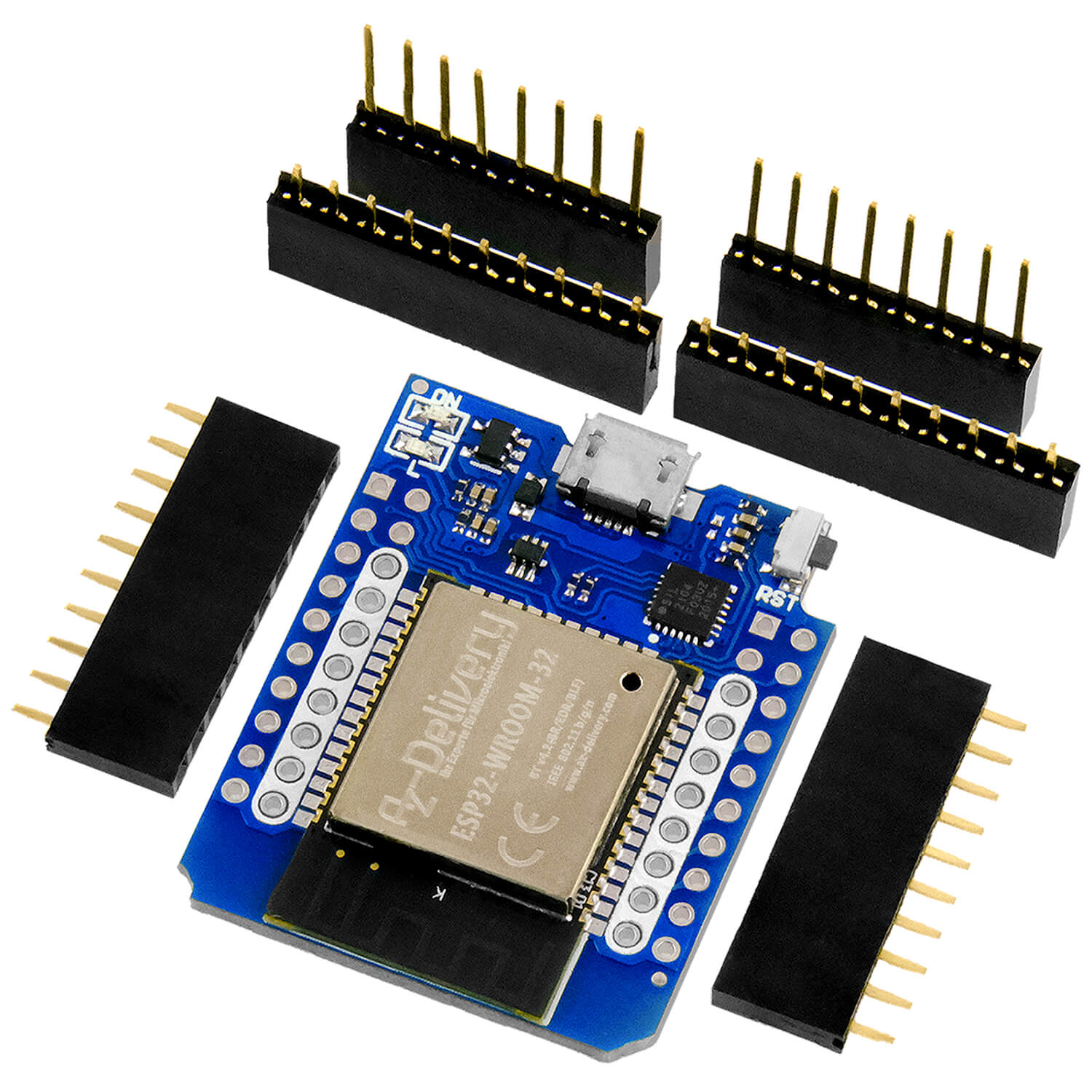
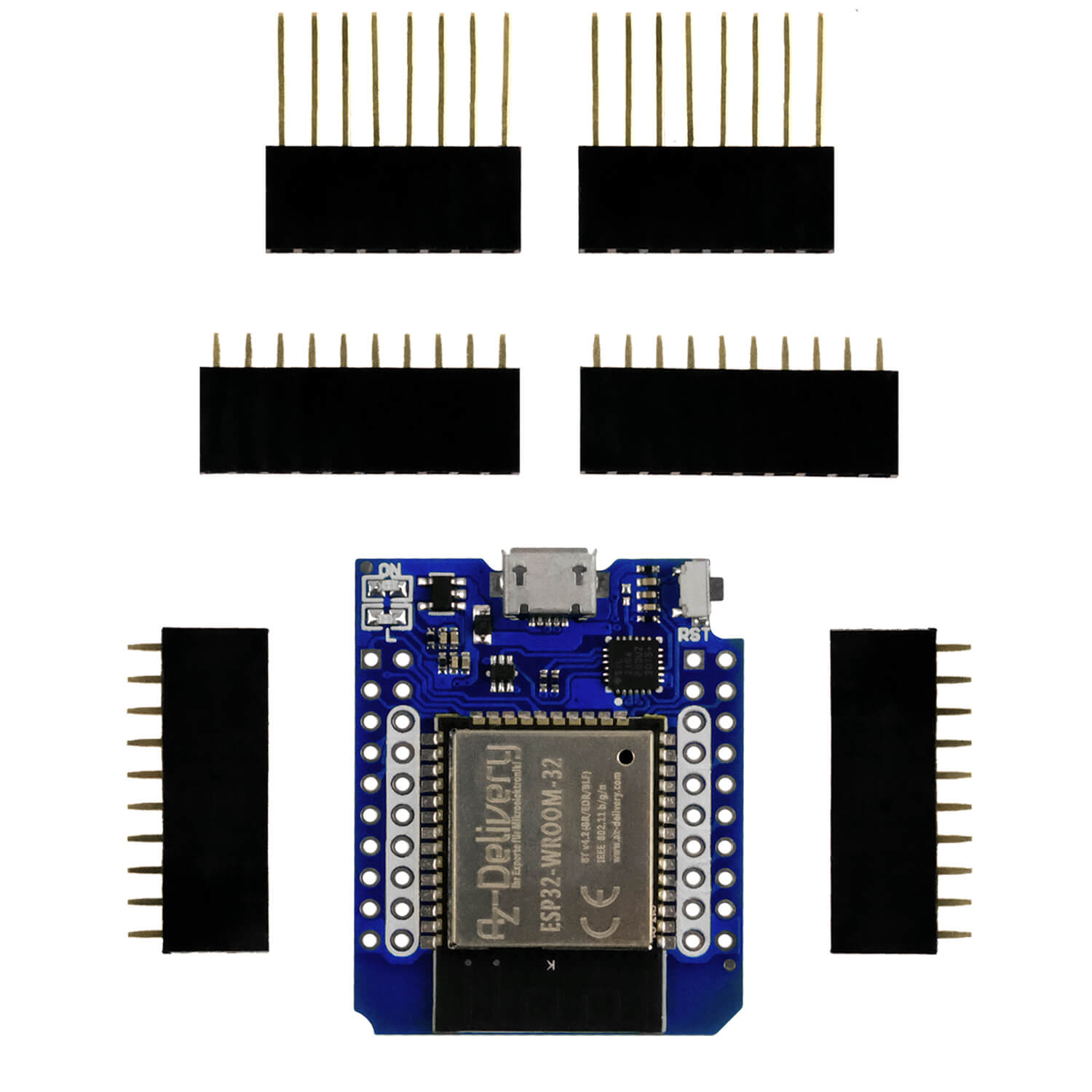
| 1 | ESP32 Dev Kit C unpleasant or ESP32 NODEMCU Module WiFi Development Board or Nodemcu-ESP-32S kit |
|---|---|
| 1 | Ky-022 Set IR receiver |
| 1 | Ky-005 IR Infrarot transmitter transceiver module |
| 1 | 0.91 inch OLED I2C display 128 x 32 pixels |
| 1 | Breadboard Kit - 3x Jumper Wire M2M/F2M/F2F + 3 Set MB102 Breadbord Compatible with Arduino and Raspberry Pi - 1x Set |
| 1 | Ky-004 button module |
| various | Jumper Wire cable 3 x 40 pcs |
| 1 | Real Time Clock RTC DS3231 I2C real -time clock |
| 1 | TM1637 4 DIGIT 7 segment LED display module |
| 1 | Ky-018 Photo LDR resistance Photo resistor sensor |
| 1 | DCF77 receiver module |
| 2 | NPN transistor BC337 or similar |
| 1 | Resistance 1.0 kΩ |
| 1 | Resistance 10 kΩ |
| 1 | Resistance 330 Ω |
| 1 | Resistance 47Ω |
| 1 | Resistance 560Ω |
| 1 | LED (color at will) |
| 1 | Adapter PS/2 according to USB or PS/2 socket |
| 1 | Logic Analyzer |
| 1 | PS/2 keyboard |
Figure 1 shows the circuit with all parts.

Figure 1: Everything together = radio clock with IR-RC ambitions

Figure 2: DCF77 reception module on ESP32
The software
For flashing and the programming of the ESP32:
Thonny or
Logic 2 operating software From Saleae
Packet station.exe: Network terminal for TCP and UDP
Used firmware for the ESP32:
Used firmware for the ESP8266:
The micropython programs for the project:
tm1637_4.py: API for the 4- and 6-digit 7-segment display with the TM1637
ds3231.py: Driver module for the RTC module
oled.py: OLED-API
SSD1306.PY: OLED hardware driver
Buttons.py: Module for key query
dcf77.py: Driver for the DCF77 module
ir_rx-small.zip: Package for the IR reception module
irsend.py: IR broadcast module
timeout.py: Software -timer
sync_it.py: Synchronizing program with DCF77
second alarm.py: Trigger demo program to the alarm
Lern.py: Reading RC5 codes
Micropython - Language - Modules and Programs
To install Thonny you will find one here Detailed instructions (English version). There is also a description of how that Micropython firmware (As of 18.06.2022) on the ESP chip burned becomes.
Micropython is an interpreter language. The main difference to the Arduino IDE, where you always flash entire programs, is that you only have to flash the Micropython firmware once on the ESP32 so that the controller understands micropython instructions. You can use Thonny, µpycraft or ESPTOOL.PY. For Thonny I have the process here described.
As soon as the firmware has flashed, you can easily talk to your controller in a dialogue, test individual commands and see the answer immediately without having to compile and transmit an entire program beforehand. That is exactly what bothers me on the Arduino IDE. You simply save an enormous time if you can check simple tests of the syntax and hardware to trying out and refining functions and entire program parts via the command line before knitting a program from it. For this purpose, I always like to create small test programs. As a kind of macro, they summarize recurring commands. Whole applications then develop from such program fragments.
Autostart
If the program is to start autonomously by switching on the controller, copy the program text into a newly created blank tile. Save this file under boot.py in WorkSpace and upload it to the ESP chip. The program starts automatically the next time the reset or switching on.
Test programs
Programs from the current editor window in the Thonny-IDE are started manually via the F5 button. This can be done faster than the mouse click on the start button, or via the menu run. Only the modules used in the program must be in the flash of the ESP32.
In between, Arduino id again?
Should you later use the controller together with the Arduino IDE, just flash the program in the usual way. However, the ESP32/ESP8266 then forgot that it has ever spoken Micropython. Conversely, any espressif chip that contains a compiled program from the Arduino IDE or AT-Firmware or Lua or ... can be easily provided with the micropython firmware. The process is always like here described.
The alarm clock program
In addition to the modules discussed in the past episodes, we import network and socket, we need the two for WLAN traffic on the cell phone, which we currently still use with the program Pack box Replace on the PC.
XXXXXXXXXX
# alarm clock.py
#
From DCF77 import DCF77
From DS3231 import DS3231
From machine import Pin code,Softi2c, timer
From OLED import OLED
From TM1637 import TM1637
From sys import exit
From Irish import Irish
From ESP32 import RMT
import network, socket
From time import sleep
In the event that our alarm clock should later work as an access point, we award the following interfaced data.
XXXXXXXXXX
interface="AP"
IF interface=="AP":
# ****************
client=("192.168.0.2",9091) # Mobile
myip="192.168.0.1"
myport=9091
server=(myip,myport) # ESP32
# **** Enter your own access data here ****
myssid = 'Antares99' # Credentials ESP32
mypass = 'GreenCacadu'
But then you can't do it pack box access. Therefore, in the test phase we use the WLAN router to build a contact. Please remember to register the ESP32 with its MAC address on the router.
XXXXXXXXXX
elif interface=="Sta":
# ******************* *******************
myip="10.0.1.96"
myport=9091
# **** Enter your own access data here ****
myssid = 'Empire_of_ants' # Credential router
mypass = 'Nightingale'
We create an I2C object and set the frequency to a safe 100kHz. The flag alarm trigger Is queried later, we are already declaring it here and put it on False. At GPIO13 is our button, which serves various purposes. We also declare the list for the Timestamp here by using a List comprehension. It creates a list of 7 zeros.
XXXXXXXXXX
I2C=Softi2c(scl=Pin code(22),sda=Pin code(23),freq=100000)
alarm trigger=False
button=Pin code(13,Pin code.IN,Pin code.Pull_up)
dt=[0 for _ in range(7)]
With the I2C instance we create an OLED object and a DS3231 object that embodies our RTC (Real Time Clock).
XXXXXXXXXX
D=OLED(I2C,Heightw=32)
RTC=DS3231(I2C)
The DCF77 object will make its signals GPIO18 Send and the LEDs to GPIO4 (Red and GPIO19 use (blue).
XXXXXXXXXX
DCF=DCF77(DCF=18,sec=4,wait=19)
The LED display is over GPIO26 (CLK) and GPIO25 (Dio) controlled. We free the display of contaminated sites.
XXXXXXXXXX
TM=TM1637(Pin code(26),Pin code(25))
TM.Clear display()
At GPIO27 Lying down, the RMT module will hand in its 38 kHz bursts in order to control the IR send LED via the transistor. The dutycycle (pulse period duration ratio) is 50%, so pulse and break have the same length.
XXXXXXXXXX
RMTPin = Pin code(27, Pin code.OUT, value = 0)
Cfreq=38000
duty=50
RMT = RMT(0, pin code=RMTPin,
idle_level=0,
clock_div=80,
tx_carrier = (Cfreq, duty, 1))
ir=Irish(RMT)
codes={}
The parameters that we have the constructor RMT() hand over second post explained. Overall, a signal with 3.3V resting level is created on the collector of the BC337, the ones of which are encoded by 38kHz-down bursts.
With codes Let us prepare the container for the RC5 codes, which later from the file commands.cfg be read. This file was created in the flash of the ESP32 in the first episode Through the course of the program Lern.py.
We want to send commands to the ESP32 via UDP protocol. For this we need a WLAN connection. During the development time of the cell phone app, this runs optimally via the WLAN router of the home network. Later the ESP32 is allowed to play Accesspoint in an island network.
The dictionary informs us about the status of the connection structure connect statusthat translates the number codes of the interface into plain text. It is suitable for both ESP32 and ESP8266.
XXXXXXXXXX
connect status = {
1000: "Stat_idle", # ESP32
1001: "Stat_Connecting",
1010: "Stat_got_ip",
202: "Stat_wrong_Password",
201: "No ap found",
5: "Unknown",
0: "Stat_idle", # ESP8266
1: "Stat_Connecting",
5: "Stat_got_ip",
2: "Stat_wrong_Password",
3: "No ap found",
4: "Stat_Connect_Fail",
}
The MAC address of the station interface of the ESP32 is usually necessary for contact with the WLAN router. That is the case when the router is involved Mac-Filtering is working. Then the MAC of the ESP32 must be registered in the filter table of the router so that the bouncer lets our controller in. Most of the time is the entry over the menu item WLAN - security of the router possible. The function hexmac() The Mac tells us in plain text.
XXXXXXXXXX
def hexmac(bytemac):
"""
The HexMac function takes the Mac address in the bytecode and
forms a string for the rehabilitation
"""
MacString =""
for I in range(0,len(bytemac)): # For all byte values
Val="{: 02x}".format(bytemac[I])
MacString += Val
IF I <len(bytemac)-1 : # Delimiter
MacString +="-" # except for the last byte
return MacString
The parameter bytemac Get the Mac address as a bytes object that can look quite cryptically. We present an empty string and then clatter bytemac Byte for byte in the for loop.
With the help of the format ring {: 02x} If we convert the byte value into a double-digit hexadecimal number string, which we tap the previous result string. Except for the last place we add a "-" as a separator.
I encoded the connection structure with functions. This makes the application and the exchange more flexible. Let's start with the Accesspoint. We create an interface object and activate it.
XXXXXXXXXX
def Setaccesspoint():
# *************
nic=network.WIRELESS INTERNET ACCESS(network.Ap_if)
nic.active(True)
Then we ask the MAC address and let it out. The break before configuring the interface has turned out to be necessary to avoid malfunctions.
XXXXXXXXXX
Mac = nic.config('Mac')# Call base Mac address and
mymac=hexmac(Mac) # convert into the succession
print("Mac station: \ t"+mymac+"\ n") # spend
sleep(1)
nic.ifconfig((myip,"255.255.255.0",myip,myip))
nic.config(essid=myssid, password=mypass)
Then we prepare a string with 10 points and set the lead counter n For 1. With the While loop, we wait until the Accesspoint interface is reported as actively and spend one more point in replay and display every second.
XXXXXXXXXX
point="............"
n=1
while need nic.active():
print(".",end='')
D.writer(point[0:n],0,2)
n+=1
sleep(1)
print("Nic Active:",nic.active())
D.clearall()
If everything worked out, we ask the configuration and have it displayed.
XXXXXXXXXX
Staconf = nic.ifconfig()
print("Sta-IP: \ t \ t",Staconf[0],"\ nsta-netmask: \ t",\
Staconf[1], "\ nsta-gateway: \ t",Staconf[2] ,sep='')
print()
D.writer(Staconf[0],0,0,False)
D.writer(Staconf[1],0,1,False)
D.writer(Staconf[2],0,2)
return nic
So that the main program can access the interface object, we give it back.
Creating a station interface object is similar. So that the access point interface does not spit into the soup, we definitely switch it off.
XXXXXXXXXX
def Connect2router():
# ************* Connect to the router
nic=network.WIRELESS INTERNET ACCESS(network.Ap_if)
nic.active(False)
What follows is almost identical with the AccessSpoint interface.
XXXXXXXXXX
nic = network.WIRELESS INTERNET ACCESS(network.Sta_if) # creates WiFi object
nic.active(True) # Nic turn on
Mac = nic.config('Mac')# Call base Mac address and
mymac=hexmac(Mac) # convert into the succession
print("Mac station: \ t"+mymac+"\ n") # spend
sleep(1)
nic.ifconfig((myip,"255.255.255.0",myip,myip))
IF need nic.Isconnected():
nic.connect(myssid, mypass)
print("Status:", nic.Isconnected())
D.writer("WLAN Connecting",0,1)
point="............"
n=1
while nic.status() != network.Stat_got_ip:
print(".",end='')
D.writer(point[0:n],0,2)
n+=1
sleep(1)
print("\ nstatus:",connect status[nic.status()])
D.clearall()
Staconf = nic.ifconfig()
print("Sta-ip: \ t \ t",Staconf[0],"\ nsta-netmask: \ t",\
Staconf[1], "\ nsta-gateway: \ t",Staconf[2] ,sep='')
print()
D.writer(Staconf[0],0,0)
D.writer(Staconf[1],0,1)
D.writer(Staconf[2],0,2)
return nic
A socket object at the network level is what a uart object is for the serial data connection via RS232, the gate through which the data exchange takes place. This is associated with a reception loop that pushes incoming characters into a receiving buffer from which we can then pick them up.
Since our transfer is to be based on the UDP protocol, we say to the constructor of the socket object that we want to use the IP-V4 family (AF_INET) and that DataGramen (sock_dgram) should be replaced.
The TCP protocol that relies on data streams would be used to transfer websites. In this case, the line -commented line is available.
During the development phase, the program must be started more often, if possible without booting the ESP32. So that this can happen every time without an error message, we tell the socket object that we want the reuse of IP address and port number (So_RuseAddr).
XXXXXXXXXX
def set():
# ***************
# Socket = socket.socket (socket.af_inet, socket.sock_stream)
sock = socket.socket(socket.Af_inet, socket.Sock_dgram)
sock.setsockopt(socket.Sol_socket,socket.So_RuseAddr,1)
sock.binding(('', myport))
print("Singing on Port",myport)
sock.set(0.1)
return sock
Then we tie the port number to the IP address that has already been awarded. So that the reception loop of the sock does not block the main program loop, we arrange a timeout of 0.1 seconds. This will certainly call up the receiving loop, however, if no data has been incorporated, waiting for those is canceled after 100ms. Of course, the socket object must also be returned because it is needed in the main program.
Various messages or commands are to be sent to the ESP32. The parser, the function parse(), tries to drop the syntax and subsequently trigger suitable actions. If something goes wrong, we will put the message back on "errors" as a precaution.
XXXXXXXXXX
def parse(Rec):
MSG="Mistake"
Two command formats are implemented.
RC: code
Get the RC5 code that the key code Corresponds to the command dictionary codes and send it over the IR LED
Alarm: 60
Put an alarm every full minute.
Alarm: minute
Set an alarm every hour at the same minute.
Alarm: hour, minute
Put an alarm every day at the same time.
First of all, we find out whether the command string contains a colon. If that is the case, then reports find() his position back, otherwise -1. We split the record at the colon in command CMD and date part data. Both are converted into capital letters, from data Let us remove a optional Newline or Carriage Return.
XXXXXXXXXX
IF Rec.find(":") != -1:
CMD,data=Rec.split(":")
CMD=CMD.upper()
data=data.upper().strip("\No")
We check the command for "RC". Is the content of data in codes To find, then we pick up the RC5 code and send it to the IR LED twice.
XXXXXXXXXX
IF CMD=="RC":
IF data in codes:
code=codes[data]
transmitter(code,2)
return "Posted"
If "alarm" was sent, different cases must be differentiated. We are looking for a comma first. Is not in data contained then can data the string Off contained, according to which an adjusted alarm2 disabled is.
XXXXXXXXXX
elif CMD=="ALARM":
IF data.find(",") == -1: # just a byte
print(data)
IF data == "Off":
RTC.Alarm(2) # Alarm2 disable
MSG= "Disabled"
print("Alarm2 from")
return MSG
time=intimately(data)
We walk the string in data to a number and point them out of the variables time to. Is time 60, the alarm is set at every full minute.
XXXXXXXXXX
IF time == 60:
RTC.Alarm2(0,0,0,RTC.every minute)
MSG= "every minute"
Lies time In the area from 0 to 59 including, then the hourly alarm will be set at this time.
XXXXXXXXXX
elif time in range(60):
RTC.Alarm2(0,0,intimately(time),
RTC.Minute alarm) #stuendlich
MSG= "In terms of {} min.".\
format(time)
Else:
Was a comma in data Discovered, there is an indication of hours and minutes. We get the shares by splitting on the comma. We send the integer values from it to the RTC for a daily alarm at the time set.
XXXXXXXXXX
H,M=data.split(",")
RTC.Alarm2(0,intimately(H),intimately(M),
RTC.Hourly alarm) #taeglich
MSG= "Taecah at {}: {}.".format(H,M)
RTC.Clear alarm(2)
return MSG
elif Rec.find("-") != -1:
data=Rec[1:].strip("\No")
code=codes[data]
transmitter(code,2)
return "Sent" + data
If an alarm is to be triggered, the ESP32 needs a GPIO input for the SQW line from the DS3231. An IRQ is released for this line, its ISR alarm call() is. The trigger is set on the falling flank. In the handler becomes alarm trigger declared as globally so that the True set value can be passed on to the main program. An ISR cannot be value with return Give back to whom? The routine was not called by any program part, but by the hardware.
XXXXXXXXXX
def alarm call(pin code):
global alarm trigger
alarm trigger=True
rtcirq=Pin code(32, Pin code.IN)
rtcirq.IRQ(handler=alarm call, trigger=Pin code.Irq_falling)
The control of the 7-segment LED display is done by the function Timeoutput(). She reads the RTC, spends the list and picks out for an hour and minute. The values are broken down into decimal digits and the corresponding segment patterns are composed into a list. We send the elements of this cunning to the corresponding segment in the for loop.
XXXXXXXXXX
def Timeoutput():
global dt
dt=RTC.DateTime()
print(dt)
house=dt[4]
minute=dt[5]
time=[TM.Segm[house//10],TM.Segm[house%10]|0x80,
TM.Segm[minute//10],TM.Segm[minute%10],]
for I in range(4):
TM.segment(time[I],I)
The processes with the DCF77 summarize the processes of a time synchronization sync() together. So that the multiplexing of the display does not interfere with the reception, we delete the display and then call dcf.Synchronize() on. The process should be completed after 2 minutes at the latest. We write the station received by the transmitter to the RTC and output the time on the display.
XXXXXXXXXX
def sync():
print("Wait at the start of the minute")
TM.Clear display()
dt=DCF.synchronize()
RTC.DateTime(dt)
Timeoutput()
print("Synchronized")
Command and address of an RC5 code must be ir.transmit() to be handed over discreetly. Therefore in transmitter() The code tupel from the dictionary codes Divided into its individual parts and then sent.
XXXXXXXXXX
def transmitter(code,rep):
AddDR,CMD,_=code
ir.transmit(intimately(AddDR),intimately(CMD),rep)
In the first episode We had the file of this series commands.cfg created in the flash of the ESP32. We are now tapping them to do the dictionary codes to fill. We present an empty dictionary and show to know what is going on in the OLED display.
XXXXXXXXXX
def readata():
codes={}
D.clearall()
D.writer("Try Reading",0,0,False)
D.writer("commands.cfg",0,1)
We capsules the file operations in a TRY-Except structure to get an error message if something goes wrong. We open the file under the handle F In a with block, that saves a close(f) at the end. Through wither the file is automatically closed when the block is left.
Line by line is read in and freed from control signs at the end of the line. All essential information about a code is housed in one line and separated by commas. There we separate the read string into its components. Data, address and control byte are under the key in key as a tupel on codes attached.
XXXXXXXXXX
try:
wither open("commands.cfg","R") AS F:
for line in F:
line=line.strip("\No")
key,data,AddDR,CTRL=line.split(",")
codes[key]=(data,AddDR,CTRL)
D.writer("Got key codes",0,1)
sleep(3)
D.clearall()
return codes
except Oserror AS E:
D.writer("Not found",0,2)
sleep(3)
D.clearall()
return None
We approach the main loop and make the final preparations. The watch is synchronized when the program starts when we remove the comment sign in the next line. During the development, I commented on this line so that I don't have to wait two minutes every time I could continue.
XXXXXXXXXX
# Sync ()
IF interface=="AP":
nic=Setaccesspoint()
elif interface=="Sta":
nic=Connect2router()
sleep(3)
Depending on the occupancy of interface Let us now provide the corresponding interface. Three seconds to read the message on the display. Then we put on the socket and read the RC5 code relay. Output in Repl and time display in the LED display.
XXXXXXXXXX
S=set()
codes=readata()
print(codes)
Timeoutput()
Alarm timer 1 brings the current time to the LED display every full minute. We switch on alarm 2 briefly to deactivate it again immediately.
XXXXXXXXXX
RTC.Alarm1(0,0,0,0,DS3231.Secondary alarm) # for the full minute
RTC.Alarm2(0,12,5,DS3231.Minute alarm)
RTC.Alarm(2)
RTC.Clear alarm(1)
RTC.Clear alarm(2)
print("Alarm:",RTC.Tell alarm status())
alarm trigger=False
The alarm flags of both alarms are reset to ensure a new alarm safely. The management SQW of the DS3231 goes to 3.3V. We can display the stand of the flags. The flag alarm trigger we put on False And get into the main loop.
XXXXXXXXXX
RTC.Alarm1(0,0,0,0,DS3231.Secondary alarm) # for the full minute
RTC.Alarm2(0,12,5,DS3231.Minute alarm)
RTC.Alarm(2)
RTC.Clear alarm(1)
RTC.Clear alarm(2)
print("Alarm:",RTC.Tell alarm status())
alarm trigger=False
while 1:
An alarm was triggered when alarm trigger on True stands. We get the alarm status, spend it and put the flag back.
XXXXXXXXXX
IF alarm trigger:
status=RTC.Tell alarm status()
print("Triggered:",RTC.Tell alarm status())
alarm trigger=False
We have a minute alarm when the Bit 0 is in the status. Now a time update in the LED display has to take place. Before that, we reset the interrupt flag of the DS3231. The output indicates whether the interrupt flag 1 was deleted.
XXXXXXXXXX
IF status & 0x01:
RTC.Clear alarm(1)
print("Alarm1:",RTC.Tell alarm status())
Timeoutput()
An hourly or daily alarm is available when BIT 1 is set in the status. After reset the IRQ flag, I send the command 1 to the address 0 twice to my RC5 device, which is switched on. The output indicates whether the Interruptflag 2 was deleted.
XXXXXXXXXX
IF status & 0x02 & RTC.Tellalarmenbled():
RTC.Clear alarm(2)
print("Alarm2:",RTC.Tell alarm status())
transmitter((0,1,0),2) # ((AdDR, CMD), Repeat)
The RTC is synchronized once a day at 3:01 a.m.
XXXXXXXXXX
IF dt[4:6] == [3,1]:
sync()
The reception of UDP messages must be encapsulated in Try Except. Were ... By recvfoma() No signs registered, then the reception loop is left and an exception is thrown that we have to intercept.
XXXXXXXXXX
try:
Rec,ADR=S.recvfoma(150)
Rec=Rec.decode().strip("\ r \ n")
reply=parse(Rec)
print(Rec,ADR)
S.broadcast(reply,ADR)
except:
passport
If a command has arrived from the cell phone, then delivers recvfoma() A record, with the message and the IP socket of the sender. Rec Contains a bytes object that we have with decode() convert into a string from which the control signs are removed. We send the prepared text to the Parser, which returns a comment string. We send it back to the sender. We will be the same as the sender Packet station.exe Use on the PC for a first test.
The next lines tell us that an alarm was triggered by Timer 2.
XXXXXXXXXX
IF RTC.Tell alarm status() & 0x02:
print("Alarm2 Triggered")
RTC.Clear alarm(2)
In order to be able to leave the program clean, we ask the button. If it was pressed, then we put on the IRQ handler of the RTC interrupt None and end the program with exit().
XXXXXXXXXX
IF button.value() == 0:
rtcirq.IRQ(handler=None)
exit()
The test with packaging transmitter
Network connections can be used Packet station.exe Test very well. The free program can send and receive UDP or TCP messages. You just have to set a local port for the PC, the IP address is automatically taken over by the network card. Then you enter the opposite side of the opposite side and select the protocol. The own message is by clicking on Send transmitted and a possible answer displayed.
Start the program now alarm clock.py In the editor window of Thonny and pack box On the PC. Figure 3 shows the settings and the answer to the command Alarm: off.

Figure 3: The window of packaging transmitters
You can now set an alarm in the same way.
Alarm: 15.33

Figure 4: Set alarm 2
Here is the Repl expense of Thonny.
alarm: 0
Off
Alarm2 out of
alarm:off ('10.0.1.10', 9091)
…
alarm:15,33 ('10.0.1.10', 9091)
…
triggered: 3
Alarm1: 2
[2023, 9, 6, 3, 15, 33, 0]
Alarm2: 0
Also send an RC5 code to your device with a packaging transmitter and check whether it reacts correctly.
RC: Off
Has it switched off? Well! You can find a stronger transmission diode at Reichelt: GRV IR Trans. It has a specified range of 10 meters.
In the next blog sequence we will make an Android app with which we can control the ESP32.
Stay tuned!