
In this project we will work with strength-sensitive pressure sensors to create an alarm that warns us visually and acoustically of manipulation of a figure issued in a showcase. The figures are illuminated with a white light. When you are manipulated, the color of the lighting changes to red and an alarm sounds. Even if we put the figure back in its place, the color of the light does not change and the alarm continues to sound to find out which figure was manipulated. Let us first explain what a strength -dependent sensor is.
What are resistant strength -dependent sensors?
The Force Sensitive resistor (FSR) Sensors are sensors that output the physical pressure exerted on them as a voltage value. This is basically variable resistors.
As a rule, these sensors consist of a conductive substrate layer and a semiconductor substructure layer, whereby these two layers are separated with adhesive on the edges by an open layer of distance. The more pressure is exerted on the active zone of the sensor, the more points in this zone touch the semiconductor layer and let the resistance value drop.

FSR are basically resisting that change their resistance value (in Ohm Ω), depending on how much they are pressed. These sensors are very easy to use, but are not very precise. They do not deliver exact values. It is possible to determine a weight with these sensors. However, you have to convert the resistance value into a proportional weight. The weight is then not exactly. However, it is possible to recognize a change. This allows the sensor to be used for this project.


The module we will use consists of the FSR sensor and a 510 kΩ resistance in series with the sensor. The circuit is supplied with 5 VDC and the output signal voltage of the circuit is removed from the voltage divider, which is formed by the 510 KOHM resistance and the FSR sensor. If the FSR sensor is not pressed, it looks like an infinite resistance (open circuit), so that the current flowing by the module is very low and the output signal voltage is very low. Conversely, the sensor's resistance drops when the pressure increases on it, so that the voltage on the output signal of the module increases. In our project, we will connect the output signal of the module to the analogue input of the AZ microcontroller and display the measured value on the serial monitor. The following figure is the circuit of the module from the AZ-Delivery-Data sheet:

Required hardware
- 1 Microcontroller Board AZ-ATMEGA328 board with USB cable
- 3 Flexible thin film pressure sensor
- 3 LED ring 5V RGB WS2812B 12-bit 37mm
- Ultra -lexified tinned silicone cable switching loads kit
- 1 SYB-1660 solder-free Breadboard Protoboard | Breadboard kit
- 1 Mini-MP3 player DFPlayer Master module
- 1 DFPlayer Mini 3 Watt 8 Ohm Mini loudspeakers
- 1 1K OHM resistance
Required software
- Arduino id
- DFPlayer mini library from Dfrobot (Dfrobotdfplayermini.h)
- Adafruit Neopixel Library for WS2812B Ring (Adafruit_neopixel.h)
- flex_print_sensor_alarm.ino
- 1.mp3 Sound file
Circuit and description of the modules used

We use three pressure sensors for three objects. You will shed light on the WS2812B LED rings with white or red light. We also use the mini-MP3 player DFPlayer together with the mini speakers to play the alarm tone. The whole thing is controlled by an AZ-Atmega328 microcontroller. We also need a microSD card to save the sound file. The whole set is operated with an external 5 VDC power supply.
Description of the program flow and sketch
While the objects are in position, the FSR sensor module has a high output signal that is displayed in the serial monitor. The LED rings illuminate the figures or objects with white light. As soon as one of the objects is manipulated, the output signal of the FSR sensor module drops, the LED ring of the manipulated object illuminates red and the alarm sounds. Even if the same or another object is positioned again in its place, the alarm remains.


The first two libraries are needed to use the Mini MP3 Player DFPlayer module. The necessary communication between the MP3 module and the microcontroller is serial. The library Softwareerial.H Contains the functionality for the microcontroller to activate any digital PIN for serial communication. With the library Dfrobotdfplayermini.h Let us activate the necessary functionalities to use the MP3 player module.
#include <Software.H>
#include <Dfrobotdfplayermini.H>
The third library is Neopixel From Adafruit to be able to use the LED rings.
#include <Adafruit_neopixel.H>
After we have integrated the necessary libraries for our project, we start creating the objects and the definition of the variables. To use the MP3 Player module, we have to MySoftwareerial object the library Softwareerial.H to implement. The digital pins are given to the microcontroller, which we will use for the serial communication of the module. We use the digital PIN 5 to receive data from the MP3 module and the digital PIN 6 to send data to the MP3 module. In order to use the module's tax methods and commands, such as setting the volume, or starting the playback of a MP3 file, we create the object mydfplayer From the library Dfrobotdfplayermini.h.
Software mysoftware(5, 6);
Dfrobotdfplayermini mydfplayer;
The outputs of the FSR sensors are connected to the analog inputs of the microcontroller. The following variables are declared for this. We also save the signals in other variables.
intimately sensor_flowers_pin = A1;
intimately sensor_flowers_signal;
intimately sensor_menina_pin = A2;
intimately sensor_menina_signal;
intimately sensor_hand_pin = A3;
intimately sensor_hand_signal;
The next four lines of the sketch are three constants for the connections of the WS2812B LED rings to the digital pins of the microcontroller and the constant for defining the number of LEDs of each ring, in this case 8 LEDs.
#define Hand_Ring_Led 4
#define menina_ring_Led 3
#define floers_ring_led 2
#define Number_leds_ring 8
For the operation of each WS2812B LED ring, an object of the Neopixel library must be created for each ring used. The respective number of LEDs of a ring is written in the arguments of this object (we have the variable for this Number_leds_ring), the pins of the microcontroller to which each ring is connected (for this we have the variables e.g. floers_ring_led), as well as the properties of every ring. They are three -colored LEDs (Neo_grb) and the working frequency is 800 kHz (Neo_khz800).
Adafruit_neopixel Flowers_ring(Number_leds_ring, floers_ring_led, Neo_grb + Neo_khz800);
Adafruit_neopixel menina_ring(Number_leds_ring, menina_ring_Led, Neo_grb + Neo_khz800);
Adafruit_neopixel Hand_ring(Number_leds_Ring, Hand_Ring_Led, Neo_grb + Neo_khz800);
Declarize and define variables for the RGB values of the two colors of each ring in the next lines of the sketch.
uint32_t floers_color_red = Flowers_ring.Color(150,0,0);
uint32_t floers_color_white = Flowers_ring.Color(150,150,150);

uint32_t menina_color_red = menina_ring.Color(150,0,0);
uint32_t menina_color_white = menina_ring.Color(150,150,150);

uint32_t Hand_color_red = Hand_ring.Color(150,0,0);
uint32_t Hand_color_white = Hand_ring.Color(150,150,150);
The next block is set up(), in which we configure the initial state of the modules.
In the first two lines we initialize serial communication with the instructions Begin ("baud rate"), both for communication with the MP3 module with the instruction MySoftwareerial.begin (9600), as well as with the serial monitor with the instruction Serial.begin (115200).
mysoftware.Begin(9600);
Serial.Begin(115200);
Next we check whether our MP3 module has been correctly initialized by a IF statement use. In the condition, we check whether the MP3 module has not been initialized for any reason. We have initialization with the symbol "!"Degrated, i.e. If the module is not initialized, the condition is true and the code within the curly brackets is carried out. If the MP3 player module is correctly initialized, the condition is not met and the code explained by us is not executed . The set up()-Methods continue to be carried out to the serial console with the line Serial.println (f ("correct dfplayer initialization.")) to inform that the MP3 player module was correctly initialized.
IF (!mydfplayer.Begin(mysoftware)) {
  Serial.print(F("Error Initializing MP3 Module:"));
  Serial.print(F("1. Please check the Connections!"));
  Serial.print(F("2. Please insert the microsd memory!"));
  while(true){
    delay(0);
  }
}

Serial.print(F("Correct dfplayer initialization."));
After initialization of the MP3 module, the three LED rings must be using the method Begin () of the object of each ring (name_ring.begin ()) to be initialized. Then we switch off all LEDs if one of them lights up.
Flowers_ring.Begin();
menina_ring.Begin();
Hand_ring.Begin();

Flowers_ring.clear();
menina_ring.clear();
Hand_ring.clear();
First of all, we set the brightness of the ring light to a value of 200 out of a total of 254.
Flowers_ring.setbrightness(200);
In one for loop All LEDs of a ring are with flowers_ring.Setpixelcolor (I, floers_color_white) configured with white lighting and then with floers_ring.show () turned on. The maximum value of the count variables I Is the value of the variable Number_leds_Ringthat we defined at the beginning.
for (intimately I=0; I<Number_leds_Ring; I++) {
  Flowers_ring.setpixelcolor(I, floers_color_white);
  Flowers_ring.show();
}
The two for loops Similar to the other two LED rings.
Only the variables for the signal values of the FSR modules follow, which are defined with a high value. We remember that the signal value of the module is high when the sensor is pressed. While its value is low when it is not pressed.
sensor_flowers_signal = 900;
sensor_menina_signal = 900;
sensor_hand_signal = 900;
With these lines the programming of the block is set up() completed. Now let's start with that Loop ()that is continuously carried out. It determines whether one of the figures has been moved or removed from their position. We will describe the code of the flowers of the flowers. The code of the figure of the menina and the hand is the same, only the value of the variables of each figure changes. That of the menina is sensor_menina_signal <1200 And that is the hand sensor_hand_signal <1000.
To check the change in the starting value of the FSR sensor module, we use a if, at which we check the previously stored value of the sensor variable of the corresponding number. The code for the three figures is the same, only the test value of the variables of each figure changes. Here, too, we will be the code to check the variables of the figure of the flowers sensor_flowers_signal analyze.
Whenever the previously in the variable sensor_flowers_signal The stored value is smaller than 1000, the interior of the block is executed.
IF (sensor_flowers_signal < 1000) {
        . . . . .
        . . . . .
As soon as we enter the instruction block, we read the current value of the signal of the FSR sensor module with the first line Analogread (sensor_flowers_pin) and save the value in the corresponding variable sensor_flowers_signal. Then we spend the value in the serial monitor.
sensor_flowers_signal = analogead(sensor_flowers_pin);
Serial.print("Sensor Flowers Reading =");
Serial.print(sensor_flowers_signal);
In the following If - Else IF it is checked whether the current value of the variable sensor_flowers_signal The object was moved less than 200, if this condition is true, the object was moved and the following code is executed to trigger the alarm.
IF (sensor_flowers_signal < 200) {
  . . . .
  . . . .
We issue a note in the serial monitor:
Serial.print("The Flowers Have Been Manipulated !!!!");
We set the intensity of the brightness of the ring light to a value of 200 out of a total of 254.
Flowers_ring.setbrightness(200);
In order to then switch on all LEDs of the affected ring in red, we use one again for loop, to go through all LEDs of the ring. The count variable I Corresponds to the number of the LED. The red lighting is with flowers_ring.Setpixelcolor (I, flexers_color_red) configured. Then they will be with floers_ring.show () turned on. We remember that the maximum value of the variables I and thus the demolition condition of the value of the variables Number_leds_Ring is.
for (intimately I=0; I<Number_leds_Ring; I++) {
  Flowers_ring.setpixelcolor(I, floers_color_red);
  Flowers_ring.show();
}
Now we have to play the alarm tone, which we on the microSD card under the name 1.mp3 Have saved. First we configure the playback strength with us mydfplayer.volume (10) and play the sound file in a loop mydfplayer.loop (1). The sound file has a period of 7 seconds. It is played until the microcontroller is reset because it is an alarm, the state of the figure should be checked. I have one Delay (500) used in the sketch so that the alarm tone is played before the next instruction is carried out.
mydfplayer.volume(10);
mydfplayer.loop(1);
delay(500);
Up to this point the code of the IF-Instructions designed as long as the value of the FSR sensor variable is smaller than 200. However, if the stored value of the updated measured value variable of the FSR sensor module is less than 1000, but larger or equal 200, the code of the Else IFInstruction. It simply informs about the serial monitor that the corresponding figure was not manipulated.
Else IF (sensor_hand_signal < 1000) {
  Serial.print("Flowers are ok and Have not been manipulated.");
}
The code for all three figures is almost the same, only the test area of the variables with the FSR sensor values of each figure changes.
If the video is not displayed, you must change the cookie settings of your browser.
additions
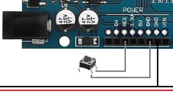
Several options can be added to the project. The first option would be to install an external button connected between a GND connection and the reset connection of our microcontroller. In this way we would reset the microcontroller that it would have the same function as the reset button of the microcontroller. The following assembly should be added to the circuit:
A second option would be to install a switch on the positive line (red cable) of the speaker. With this other arrangement, only the alarm would stop if the switch was flipped, but the figure's LED rings would continue to light up red to display which of the figures was manipulated. With this second option we have to make sure to change the switch to reactivate the sound after we have checked the status of the characters.

We hope that this project forms the basis for the development of its own projects, such as: B. the detection of the penetration into a room.


2 Reacties
Helmut van Kan
Ich habe die Schwelle für den Sensor auf 10 herabgesetzt. Das reichte aus für einen kleinen Basaltstein von 130 g Gewicht. Allerdings muss das Gewicht dann auch möglichst punktförmig auf den Sensor wirken. Zur Unterstützung habe ich im Setup des Programms ein Stück Code eingefügt, das die LED_BUILTIN einschaltet, wenn die Sensorschwelle überschritten ist. Außerdem habe ich eine Warteschleife eingebaut, die die Überwachung erst dann scharf schaltet, wenn die Sensorschwelle für mehrere Sekunden überschritten ist.
Imke
Cooles Projekt 😎
Wie schwer müssen bzw. dürfen die Objekte sein, damit der Sensor korrekt arbeitet?